| This is the
talk page for discussing improvements to the
Ambient occlusion article. This is not a forum for general discussion of the article's subject. |
Article policies
|
| Find video game sources: "Ambient occlusion" – news · newspapers · books · scholar · JSTOR · free images · free news sources · TWL · NYT · WP reference · VG/RS · VG/RL · WPVG/Talk |
|
| This article is rated C-class on Wikipedia's
content assessment scale. It is of interest to the following WikiProjects: | ||||||||||||||||||||
| |||||||||||||||||||||


Total and utter crap, this article must be rewritten from scratch. — Preceding unsigned comment added by 79.52.243.58 ( talk) 19:38, 19 March 2013 (UTC)
This picture needs shadows to illustrate the point better, even though this isn't an article about shadows. It looks wrong without them, and they would be used in a real-life application. Same with the combined picture. Erudecorp 22:09, 22 October 2007 (UTC)
- Technically the combined picture has shadows... shadows are simply the consequence of an occluded light source. In the combined image a spherical light source is correctly occluded by the bug geometry. I'm guessing you're referring to shadows from a highly directional light source, though I'm not convinced this is a relevant comparison here. (Convince me that it is! :) Trevorgoodchild 01:20, 23 October 2007 (UTC)
- Yes! That is what I'm referring to. I don't think you'll need any convincing once you see what I mean. The second picture (diffuse only) uses a directional light (or two). But no shadows (occlusion, like you said). So the third image only gets shadows from the sky box, not from the directional light. It's also odd that the third image is darker, even though it has two lighting models. It think the maker of the images put them into Photoshop as two layers, and multiplied them, instead of screening them. It's true that the spherical light source is occluded, but not the directional light. The person that made the original set of images hasn't done anything since 2005. Can you remake the three images? Erudecorp ? * 22:59, 23 October 2007 (UTC)
- The diffuse only uses just ONE light, with lambert-shading, with the lamp at the same spot as the camera, just try it in any 3d editor and you'll see it's just like that... Plus, all shadows cast by this light are behind whatever casted that shadow, like the bug limbs... Besides, 3rd image is darker because it indeed multiplies, 0 being black and 1 being white. but that makes: white * black = black, thus making it darker. But what I think would be even more easy for 3d viewing would be ambient occlusion + Z/distantfog/(whatever it's called, farther blacker and closer brighter), I ran a few tests with a head model I have and it was even best for viewing the 3d-ness of the object that way. 189.5.88.158 ( talk) 05:10, 15 June 2008 (UTC)
"Ambient occlusion" doesn't actually represent any real-world optical effect, it's a very rough approximation of shadows that "looks better" in many cases, but it produces a number of effects that are just plain wrong. In the real world, for example, you don't get dark regions at the intersection of two plane surfaces (the corner of a room, for example) simply from ambient light... yet this is a classic example trotted out to "demonstrate ambient occlusion". Try it... take some photographs of matte painted corners in a diffusely-lighted environment, any place where two corners actually come together the lighting is uniform all the way to the intersection. The only places I have been able to see such shadows is when you've got a nearby point source, and the corners are darker simply because they're further from the source... and there are better ways to simulate that effect! -- Resuna ( talk) 19:10, 21 July 2008 (UTC)
- I think it's not only meant to look generally better, I think it's got something to do with emulating radiosity with fewer processor usage. Though it should reflect in the surfaces until it hit the 'outside' to make the proper calculation, ending in being almost as processor consuming as radiosity, I guess... Dunno... I saw it somewhere saying it got something to do with radiosity, dunno where... 189.5.88.158 ( talk) 18:06, 13 August 2008 (UTC)
- Looks like images from a Scanning electron microscope - co-incidence ? -- 195.137.93.171 ( talk) 09:00, 6 May 2010 (UTC)
Hello all...
An image used in the article, specifically Image:Aocclude hemisphere.png, has a little bit of a licensing issue. The image was uploaded back when the rules around image uploading were less restrictive. It is presumed that the uploader was willing to license the picture under the GFDL license but was not clear in that regard. As such, the image, while not at risk of deletion, is likely not clearly licensed to allow for free use in any future use of this article. If anyone has an image that can replace this, or can go take one and upload it, it would be best.
You have your mission, take your camera and start clicking.-- Jordan 1972 ( talk) 22:11, 29 September 2008 (UTC)
- And take a picture of what? It wasn't like this was a picture of a horse or a car. —Preceding unsigned comment added by 72.181.253.68 ( talk) 01:49, 10 December 2008 (UTC)
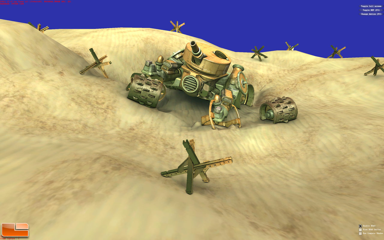
- You can replace with image from here:
- http://www.legitreviews.com/article/1040/2/
- http://www.legitreviews.com/images/reviews/1040/hdao_on_large.jpg
- (black lines simulate shadows around objects). It gives realism (in open places) but unrealism too at some conditions (inside room with one windows and dark or black painted walls etc.).
Am I correct, that ambient occlusion came to computer games graphics first time with directx 10.1 version or earlier?
- I don't know if it first was included in DirectX in version 10.1, but I'm sure that when it came to DirectX, it had already been implemented in video games for a while already. Also, please sign you comments with four tildes (~~~~) so it is possible to see who is writing. — Kri ( talk) 15:52, 12 October 2011 (UTC)
It seems, that ambient lighting only comes from above, but sky or clouds illuminating light from all directions except earth. So 5 parallel light sources (with light colour of each plane depending on skybox average colour, somthing like, where no clouds colour blue and where is clouds light colour more bright blank blue) can give much realism, only don't need use shadows, but only for diffuse illumination of object (depending on angle between light and object surface normal). But if use shadows some blur can be if it is possible. Of course some half sphere from inside lighting would be almost exact model except coulours (light can't change colour if sky have bright clouds or not), but it's almost impossible, so 5 planes should do we trick, if for example from one side is object blocked with over object, then diffuse little bit changing, even if there no sun in sky (sun under big clouds). Maybe ambient occlusion is that I talking, for example instead 5 lights, to use 20 lights and to blur all shadows somehow. In such way we get ambient occlusion and some diffuse lighting from sky. — Preceding unsigned comment added by Versatranitsonlywaytofly ( talk • contribs) 21:56, 24 November 2011 (UTC)
- There is more effective way, which for simple objects like spheres works almost 100% exactly like in real world. It is called
- Hemisphere Lighting Model
- When dealing with an outdoor environment,
you can simplify the process even more because the most important components of the lighting are the sky and ground reflection colors. Going with this assumption, the process of finding out the total lighting for a particular microfacet of your object becomes a matter of determining the appropriate blend of both the sky and ground colors. This process is illustrated in Figure 17.3. Note that this approach can work well for any circumstance when lighting can be simplified by the representation of two sources of light, one coming from the ground and the other from above, and is not restricted to only outdoor scenes, although it is the most obvious example. To achieve the appropriate blend, you need to determine the proportion of the microfacet hemisphere that corresponds to the sky and ground portions. Without getting into the mathematical details, such integration is simply a matter of interpolating the sky and ground color in relationship to the dot product of surface normal and a vector pointing towards the sky. Doing so yields the following vertex shader code:
blendFactor = (dot(inNormal, float3(0,-1,0)) + 1.0)/2.0;
- To develop a shader using this technique, you need a one-pass effect that renders an
object, taking in both the position and the normals for the object vertices. In addition to the standard components, you need two extra variables to store the color of the ground and sky.With this, your vertex shader simply needs to take in the vertex normal, compute the blending factor, and use the lerp function to blend both colors. The following is the resulting vertex shader:
float4x4 view_proj_matrix;
float4 sky_color;
float4 ground_color;
struct VS_OUTPUT
{
float4 Pos: POSITION;
float4 Diff: COLOR;
float4 Tex: TEXCOORD;
};
VS_OUTPUT vs_main(
float4 inPosition: POSITION,
float4 inNormal: NORMAL,
float4 inTex: TEXCOORD )
{
VS_OUTPUT Out;
// Transform the position and output the texture coordinate
Out.Pos = mul( view_proj_matrix, inPosition);
Out.Tex = inTex;
// Determine the sky/ground factor
float factor = (dot(inNormal, float3(0,-1,0)) + 1.0)/2.0;
// Determine final lighting color
Out.Diff = lerp(sky_color,ground_color,factor);  // lerp(x, y, z)=x+z*(y-x) and lerp(x, y, 0.5)=(x+y)/2
Out.Diff.a = 1.0;
return Out;
}
// For example:
// float factor = (dot(float3(0.6, 0.8, 0), float3(0,-1,0)) + 1.0)/2.0; //factor=([0.6*0+0.8*(-1)+0*0]+1)/2=(-0.8+1)/2=0.1
// Out.Diff = lerp(sky_color,ground_color,factor); // Out.Diff=float3(0, 0.75, 1)+0.1*(float3(0, 0.5, 0)-float3(0, 0.75, 1))=
// =float3(0, 0.75, 1)+0.1*float3(0, -0.25, -1)=float3(0, 0.75-0.025, 1-0.1)=float3(0, 0.725, 0.9)
// Another example if clear sky and sun illuminating grass:
 // float factor = (dot(float3(0.866, 0.5, 0), float3(0,-1,0)) + 1.0)/2.0; //factor=([0.866*0+0.5*(-1)+0*0]+1)/2=(-0.5+1)/2=0.25
// Out.Diff = lerp(sky_color,ground_color,factor); // Out.Diff=float3(0, 0.75, 1)+0.25*(float3(0, 1, 0)-float3(0, 0.75, 1))=
// =float3(0, 0.75, 1)+0.25*float3(0, 0.25, -1)=float3(0, 0.75+0.0625, 1-0.25)=float3(0, 0.8125, 0.75)
// this is result if not counting [in] direct sun lighting on triangle (on microfacet)
- The pixel shader simply needs to take in the determined lighting color and modulate this
interpolated value with the texture color of your object, yielding the following pixel
shader code:
sampler color_map;
float4 ps_main(
float4 inDiff: COLOR,
float4 inTex: TEXCOORD ) : COLOR
{
// Return the hemisphere color modulated
// with the color of the base texture
return inDiff * tex2D(color_map, inTex);
}
- Keep in mind that this particular shader does its operations
on a per-vertex basis but can easily be adapted to do the same in a per-pixel (bump mapped surface normal taken) manner.
- Why is this technique so awesome? There are a few
reasons worth mentioning; the first is the quality of the rendering results versus its ease of implementation. It is essentially a great, low-cost way of representing ambient lighting.
there are
- Broad Temporal Ambient Obscurance developed by Microsoft
- Multi-scale Volumetric Occlusion used by Unity
| This is the
talk page for discussing improvements to the
Ambient occlusion article. This is not a forum for general discussion of the article's subject. |
Article policies
|
| Find video game sources: "Ambient occlusion" – news · newspapers · books · scholar · JSTOR · free images · free news sources · TWL · NYT · WP reference · VG/RS · VG/RL · WPVG/Talk |
|
| This article is rated C-class on Wikipedia's
content assessment scale. It is of interest to the following WikiProjects: | |||||||||||||||||||||||||||||||||||||||||
| ||||||||||||||||||||||||||||||||||||||||||
Total and utter crap, this article must be rewritten from scratch. — Preceding unsigned comment added by 79.52.243.58 ( talk) 19:38, 19 March 2013 (UTC)
This picture needs shadows to illustrate the point better, even though this isn't an article about shadows. It looks wrong without them, and they would be used in a real-life application. Same with the combined picture. Erudecorp 22:09, 22 October 2007 (UTC)
- Technically the combined picture has shadows... shadows are simply the consequence of an occluded light source. In the combined image a spherical light source is correctly occluded by the bug geometry. I'm guessing you're referring to shadows from a highly directional light source, though I'm not convinced this is a relevant comparison here. (Convince me that it is! :) Trevorgoodchild 01:20, 23 October 2007 (UTC)
- Yes! That is what I'm referring to. I don't think you'll need any convincing once you see what I mean. The second picture (diffuse only) uses a directional light (or two). But no shadows (occlusion, like you said). So the third image only gets shadows from the sky box, not from the directional light. It's also odd that the third image is darker, even though it has two lighting models. It think the maker of the images put them into Photoshop as two layers, and multiplied them, instead of screening them. It's true that the spherical light source is occluded, but not the directional light. The person that made the original set of images hasn't done anything since 2005. Can you remake the three images? Erudecorp ? * 22:59, 23 October 2007 (UTC)
- The diffuse only uses just ONE light, with lambert-shading, with the lamp at the same spot as the camera, just try it in any 3d editor and you'll see it's just like that... Plus, all shadows cast by this light are behind whatever casted that shadow, like the bug limbs... Besides, 3rd image is darker because it indeed multiplies, 0 being black and 1 being white. but that makes: white * black = black, thus making it darker. But what I think would be even more easy for 3d viewing would be ambient occlusion + Z/distantfog/(whatever it's called, farther blacker and closer brighter), I ran a few tests with a head model I have and it was even best for viewing the 3d-ness of the object that way. 189.5.88.158 ( talk) 05:10, 15 June 2008 (UTC)
"Ambient occlusion" doesn't actually represent any real-world optical effect, it's a very rough approximation of shadows that "looks better" in many cases, but it produces a number of effects that are just plain wrong. In the real world, for example, you don't get dark regions at the intersection of two plane surfaces (the corner of a room, for example) simply from ambient light... yet this is a classic example trotted out to "demonstrate ambient occlusion". Try it... take some photographs of matte painted corners in a diffusely-lighted environment, any place where two corners actually come together the lighting is uniform all the way to the intersection. The only places I have been able to see such shadows is when you've got a nearby point source, and the corners are darker simply because they're further from the source... and there are better ways to simulate that effect! -- Resuna ( talk) 19:10, 21 July 2008 (UTC)
- I think it's not only meant to look generally better, I think it's got something to do with emulating radiosity with fewer processor usage. Though it should reflect in the surfaces until it hit the 'outside' to make the proper calculation, ending in being almost as processor consuming as radiosity, I guess... Dunno... I saw it somewhere saying it got something to do with radiosity, dunno where... 189.5.88.158 ( talk) 18:06, 13 August 2008 (UTC)
- Looks like images from a Scanning electron microscope - co-incidence ? -- 195.137.93.171 ( talk) 09:00, 6 May 2010 (UTC)
Hello all...
An image used in the article, specifically Image:Aocclude hemisphere.png, has a little bit of a licensing issue. The image was uploaded back when the rules around image uploading were less restrictive. It is presumed that the uploader was willing to license the picture under the GFDL license but was not clear in that regard. As such, the image, while not at risk of deletion, is likely not clearly licensed to allow for free use in any future use of this article. If anyone has an image that can replace this, or can go take one and upload it, it would be best.
You have your mission, take your camera and start clicking.-- Jordan 1972 ( talk) 22:11, 29 September 2008 (UTC)
- And take a picture of what? It wasn't like this was a picture of a horse or a car. —Preceding unsigned comment added by 72.181.253.68 ( talk) 01:49, 10 December 2008 (UTC)
- You can replace with image from here:
- http://www.legitreviews.com/article/1040/2/
- http://www.legitreviews.com/images/reviews/1040/hdao_on_large.jpg
- (black lines simulate shadows around objects). It gives realism (in open places) but unrealism too at some conditions (inside room with one windows and dark or black painted walls etc.).
Am I correct, that ambient occlusion came to computer games graphics first time with directx 10.1 version or earlier?
- I don't know if it first was included in DirectX in version 10.1, but I'm sure that when it came to DirectX, it had already been implemented in video games for a while already. Also, please sign you comments with four tildes (~~~~) so it is possible to see who is writing. — Kri ( talk) 15:52, 12 October 2011 (UTC)
It seems, that ambient lighting only comes from above, but sky or clouds illuminating light from all directions except earth. So 5 parallel light sources (with light colour of each plane depending on skybox average colour, somthing like, where no clouds colour blue and where is clouds light colour more bright blank blue) can give much realism, only don't need use shadows, but only for diffuse illumination of object (depending on angle between light and object surface normal). But if use shadows some blur can be if it is possible. Of course some half sphere from inside lighting would be almost exact model except coulours (light can't change colour if sky have bright clouds or not), but it's almost impossible, so 5 planes should do we trick, if for example from one side is object blocked with over object, then diffuse little bit changing, even if there no sun in sky (sun under big clouds). Maybe ambient occlusion is that I talking, for example instead 5 lights, to use 20 lights and to blur all shadows somehow. In such way we get ambient occlusion and some diffuse lighting from sky. — Preceding unsigned comment added by Versatranitsonlywaytofly ( talk • contribs) 21:56, 24 November 2011 (UTC)
- There is more effective way, which for simple objects like spheres works almost 100% exactly like in real world. It is called
- Hemisphere Lighting Model
- When dealing with an outdoor environment,
you can simplify the process even more because the most important components of the lighting are the sky and ground reflection colors. Going with this assumption, the process of finding out the total lighting for a particular microfacet of your object becomes a matter of determining the appropriate blend of both the sky and ground colors. This process is illustrated in Figure 17.3. Note that this approach can work well for any circumstance when lighting can be simplified by the representation of two sources of light, one coming from the ground and the other from above, and is not restricted to only outdoor scenes, although it is the most obvious example. To achieve the appropriate blend, you need to determine the proportion of the microfacet hemisphere that corresponds to the sky and ground portions. Without getting into the mathematical details, such integration is simply a matter of interpolating the sky and ground color in relationship to the dot product of surface normal and a vector pointing towards the sky. Doing so yields the following vertex shader code:
blendFactor = (dot(inNormal, float3(0,-1,0)) + 1.0)/2.0;
- To develop a shader using this technique, you need a one-pass effect that renders an
object, taking in both the position and the normals for the object vertices. In addition to the standard components, you need two extra variables to store the color of the ground and sky.With this, your vertex shader simply needs to take in the vertex normal, compute the blending factor, and use the lerp function to blend both colors. The following is the resulting vertex shader:
float4x4 view_proj_matrix;
float4 sky_color;
float4 ground_color;
struct VS_OUTPUT
{
float4 Pos: POSITION;
float4 Diff: COLOR;
float4 Tex: TEXCOORD;
};
VS_OUTPUT vs_main(
float4 inPosition: POSITION,
float4 inNormal: NORMAL,
float4 inTex: TEXCOORD )
{
VS_OUTPUT Out;
// Transform the position and output the texture coordinate
Out.Pos = mul( view_proj_matrix, inPosition);
Out.Tex = inTex;
// Determine the sky/ground factor
float factor = (dot(inNormal, float3(0,-1,0)) + 1.0)/2.0;
// Determine final lighting color
Out.Diff = lerp(sky_color,ground_color,factor);  // lerp(x, y, z)=x+z*(y-x) and lerp(x, y, 0.5)=(x+y)/2
Out.Diff.a = 1.0;
return Out;
}
// For example:
// float factor = (dot(float3(0.6, 0.8, 0), float3(0,-1,0)) + 1.0)/2.0; //factor=([0.6*0+0.8*(-1)+0*0]+1)/2=(-0.8+1)/2=0.1
// Out.Diff = lerp(sky_color,ground_color,factor); // Out.Diff=float3(0, 0.75, 1)+0.1*(float3(0, 0.5, 0)-float3(0, 0.75, 1))=
// =float3(0, 0.75, 1)+0.1*float3(0, -0.25, -1)=float3(0, 0.75-0.025, 1-0.1)=float3(0, 0.725, 0.9)
// Another example if clear sky and sun illuminating grass:
 // float factor = (dot(float3(0.866, 0.5, 0), float3(0,-1,0)) + 1.0)/2.0; //factor=([0.866*0+0.5*(-1)+0*0]+1)/2=(-0.5+1)/2=0.25
// Out.Diff = lerp(sky_color,ground_color,factor); // Out.Diff=float3(0, 0.75, 1)+0.25*(float3(0, 1, 0)-float3(0, 0.75, 1))=
// =float3(0, 0.75, 1)+0.25*float3(0, 0.25, -1)=float3(0, 0.75+0.0625, 1-0.25)=float3(0, 0.8125, 0.75)
// this is result if not counting [in] direct sun lighting on triangle (on microfacet)
- The pixel shader simply needs to take in the determined lighting color and modulate this
interpolated value with the texture color of your object, yielding the following pixel
shader code:
sampler color_map;
float4 ps_main(
float4 inDiff: COLOR,
float4 inTex: TEXCOORD ) : COLOR
{
// Return the hemisphere color modulated
// with the color of the base texture
return inDiff * tex2D(color_map, inTex);
}
- Keep in mind that this particular shader does its operations
on a per-vertex basis but can easily be adapted to do the same in a per-pixel (bump mapped surface normal taken) manner.
- Why is this technique so awesome? There are a few
reasons worth mentioning; the first is the quality of the rendering results versus its ease of implementation. It is essentially a great, low-cost way of representing ambient lighting.
there are
- Broad Temporal Ambient Obscurance developed by Microsoft
- Multi-scale Volumetric Occlusion used by Unity