| This is an archive of past discussions. Do not edit the contents of this page. If you wish to start a new discussion or revive an old one, please do so on the current talk page. |
| Archive 1 | Archive 2 |
Untitled
Regarding unshielded twisted pair
If it ain't shielded, it'll short-circuit. So someone should correct this unprecise phrase, please. thanks, -- Abdull 12:08, 17 Mar 2005 (UTC)
- you mean insulated. electromagnetic shielding is different. - Omegatron
"f cancelling out electromagnetic interference kno"
- technically magnetic interference, right? only shielding cancels electric interference. - Omegatron 16:55, Apr 15, 2005 (UTC)
- Hmm.. effect of the magnetic field from one wire on the electrons from the other thus electromagnetic?? Mozzerati 19:42, 27 September 2005 (UTC)
- Well I don't think the method is efficient enough to cancel out direct magnetic interference, so the real thing it cancels out is crosstalk, which actually is EMI
- Well, actually, electric and magnetic fields are inseparable. You can't just have a magnetic field or just an electric field. They're orthogonally oriented components of each other. So both are probably canceled by the twisting.
When the wavelength is much longer than the wire length they are pretty much separate, and when it is much longer than the wire spacing they can still be treated separately.
Consider the electromagnetic field due to a nearby radio station. The induced voltage will be pretty much the same on both wires, called common-mode. That won't get through the transformer at the end.
Consider a 50Hz or 60Hz magnetic field from a nearby power cable. An untwisted cable looks like a very long and narrow wire loop, and a changing magnetic field will induce a current. Twisting with a pitch somewhat less than the wavelength causes the induced currents to change sign every half twist.
Consider two twisted pairs in the same cable. If the twist pitch is about equal, both inductive (magnetic) and capacitive (electrostatic) coupling can add over the length of the cable. (Model capacitive coupling as capacitors between the wires, larger capacitors for closer wires.) With different twist pitch, the induced current and voltage cancels over lengths somewhat longer than the shorter twist pitch.
Gah4 23:25, 22 June 2007 (UTC)
need of help
This page may need the expertise of a professional Akupta321 06:31, 18 March 2006 (UTC)
Merge stubs into this article
I have already gone ahead and merged the shielded twisted pair stub into this article. I would also like to do so with the unshielded twisted pair article. Before I do so, I'd like some other people's opinions. N. Harmon 01:35, 28 May 2006 (UTC)
I think the foiled twisted pair article should be merged into here also. N. Harmon 01:43, 28 May 2006 (UTC)
I also think we should consider merging several cable category articles into this one. N. Harmon 02:22, 28 May 2006 (UTC)
- Oppose the merger of cable category articles, but support the merger of the twisted pair variants. The cable category articles are (from what I can tell) pretty good, this article shouldn't concern itself with them. By the way, from the history I noticed that the user Mozzerati originally seperated the sections, see what he has to say. Also, take a look at all the articles pointing here and see if it is possible to improve that. In my opinion this article is in need of some serious attention, I'll help around where I can. -- Bruce 09:54, 28 May 2006 (UTC)
- Two of the cable category articles are good, specifically Category 5 cable and Category 6 cable. However they do seem to repeat a lot of information that is really about twisted pair cables and not necessarily THAT category of cable. I appreciate your thoughts on this. N. Harmon 15:37, 28 May 2006 (UTC)
- Oppose keep specialized info in seperate articles. Generic info might be merged into twisted pair. Bemoeial 12:48, 6 June 2006 (UTC)
"'oppose'" - There are hundreds of type of twisted pair cables, but "Category X" is not a generic term, it is a specific term for this particular cable. It deserves a place of it's own. Trane Engineer
"'oppose'" The information for Cat 6 cable was good, and should be in its own catagory. <pun> I would not look it up under twisted pair, I would search under Category X. Twisted pair is too general, like putting it all under "wire". 69.31.216.194 17:48, 6 June 2006 (UTC) Tom Moffatt
"'Oppose" It does take some knowledge of most types of media cable to differenciate twisted pair. It can't just be classified to just Cat5 cables! ~ T. Hansen, California
- Oppose Too much info to merge, Wikipedia is not paper. Themindset 16:15, 9 June 2006 (UTC)
- gently oppose there's a real need for a discussion of the physics, grounding characteristics etc. of the different types. I started to think about writing it, but got sidetracked. I think they are sufficiently important and different to be worthy of separate articles. On the other hand, there's nothing wrong with merging for some time and then later splitting again. Mozzerati 20:31, 9 June 2006 (UTC)
Cancelation between pairs
To me it is not obviously why two pairs in the same cable does not crosstalk a lot. It looks like they are two coils on the same transformer. I expect that they are twisted at the same rate. Appearently this is not the case and I think this article should explain why. 62.79.30.244 08:23, 12 February 2007 (UTC)
- "Why does each pair in Cat 5/5E/6 cable have different twist rates?" [1]
- "EIA-568 ... Pair Assembly: The pair twists of any pair shall not be exactly the same as any other pair. The pair twist lengths shall be selected by the manufacturer to assure compliance with the crosstalk requirements of this standard." [2]
- "... within the Cat 5 cable. Each individual phone line ... each phone line (made of two twisted strands of copper) has a "twist rate" different from the other three lines. One of the four pairs will have a high number of twists per inch, one will have a low number of twists per inch, and the other two will have twist rates somewhere in between. That difference in twist rates prevents signals from bleeding across phone lines." [3]
- "UTP (Unshielded Twisted Pair) cable rated as Category-5 typically contain (8 conductors) 4 pairs of 24 awg solid copper wire. Each of the pairs is two conductors twisted together, and each pair in a cable has a different number of twists per inch when compared to the other pairs." [4]
- "CAT5/5e/6 cables consist of four pairs of cables... the slight difference in twist rate for each pair... " [5]
- twist rate pedantry [6]
-- 76.209.28.72 18:34, 5 June 2007 (UTC)
- To simplify what the anon above has stated: Take a spare cable that you have, and remove the shielding; notice how each of the four pairs is twisted differently, with each pair having a different number of twists? Since the rate of twists for each pair is different, crosstalk (the aforementioned "bleeding") is less likely to occur. PeanutCheeseBar 19:24, 14 June 2007 (UTC)
differential vs balanced
I'm just trying to clear up misconceptions around the 'pedia about EMI and cables. As I understand it:
- "Balanced" refers to keeping the source and load impedances of a transmission line equal, so that any noise that couples into the wires will couple equally, and can be rejected at the other end.
- Twisting cancels out fields that couple into adjacent twists.
- "Differential" refers to sending signals of opposite polarity down the wires. This is so that the wire's EM fields mostly cancel out.
- Shielding does a variety of things
— Omegatron 16:05, 31 May 2007 (UTC)
Balanced and differential are essentially the same. Keeping the source and load impedance the same is matched, usually impedance matched.
Balanced means the currents (and for uniform impedance, the voltage) are equal and opposite in the two wires. Both electric and magnetic fields fall off fairly fast with distance
Yes, it is really the electromagentic field, but one can separately consider capacitive coupling (due to the electric field) and inductive coupling (due to the magnetic field). Two parallel UTP cables with the same twist pitch will have both capacitive and inductive coupling as the fields add up over the length of the cable. With different twist pitch, in the long run the coupling, both inductive and capacitive coupling average out to zero.
Note that impedance matching is not required for UTP operation. Assuming transformers are used on both ends, the reflected signal will still be balanced.
Gah4 Gah4
- Yes, matching source and load impedances is another important feature, to prevent reflections and "ringing".
- "Balanced" applies to the impedances of each line, though, not the currents or the signal. It means that both lines are driven by the same source impedance and terminated by the same load impedance (and have the same characteristic impedance?), so that any noise that couples into them will be equal in both and can be rejected. — Omegatron 23:32, 22 June 2007 (UTC)
A reference to balanced is probably applicable. It looks pretty good, but is mostly meant for low frequency (audio) applications. UTP works just find if the impedances are wrong, as long as they aren't too far off. If transformer driven, the currents will be equal and opposite, which is most important as far as EMI (radiation) is concerned. Equal impedance to ground is important, but is reasonably likely in a twisted pair cable.
Note that telephone wiring uses 600 ohm source/load but the UTP cable has much lower impedance. Yes, the impedance for each wire to ground must be (approximately) equal, but that is fairly unrelated to the cable impedance. If the impedances to ground are different then equal voltage/current in won't stay equal.
Gah4 08:08, 10 September 2007 (UTC)
I added the Historical Note, forgot to enter Edit Summary. LoopTel 19:23, 5 July 2007 (UTC)
Disagreement between advantages/disadvantages
First we say that "It is a thin, flexible cable that is easy to string between walls." Then we say that "...twisted pair cables usually have stringent requirements for maximum pulling tension as well as minimum bend radius. This relative fragility of twisted pair cables makes the installation practices an important part of ensuring the cable’s performance." Which is it? — BRIAN 0918 • 2007-09-12 15:11Z
Mains twisted pair
The article appears to have not noticed that there is also twisted pair flex that has nothing to do with data transmission, and is twisted solely because its the lowest cost way to keep 2 insulated conductors together. Such flex was in widespread use in the first world until the 1960s as mains flex, and is still sometimes found in poorer countries. Tabby ( talk) 12:13, 1 March 2008 (UTC)
Why UTP
"Unshielded twisted pair (UTP) cabling, because of its 100-year history of use by telephone systems, both indoors and out, is also the most common cable used in computer networking."
no, because its the cheapest thing that does the job. Thats more or less always the reason for such decisions. Tabby ( talk) 12:13, 1 March 2008 (UTC)
by ( http://tldp.org/HOWTO/Serial-HOWTO-5.html#ss5.2) twisted pair technology obtains higher speed Vy0123 ( talk) 04:18, 19 March 2008 (UTC)
- Compared to the serial port - does not mean much! Tabby has already said all there is to say about this subject.-- itpastorn ( talk) 09:26, 19 March 2008 (UTC)
Tabby refers to price. The tdlp refers to the principle of twisted pair technology in writing:-
All of the EIA-232 serial cable wires use a common ground return wire so that twisted-pair technology (needed for high speeds) can't be used without additional hardware.
It is somewhat tragic that the RS-232 standard from 1969 did not use twisted pair technology which could operate about a hundred times faster. Twisted pairs have been used in telephone cables since the late 1800's. In 1888 (over 115 years ago) the "Cable Conference" reported its support of twisted-pair (for telephone systems) and pointed out its advantages. But over 80 years after this approval by the "Cable Conference", RS-232 failed to utilize it.
RS-232 was mostly for connecting modems to computers, usually over a short distance. It was later that the idea of using it for longer distances came along. RS-232 also has current limited drivers, also not so good for longer distances. Gah4 ( talk) 02:04, 30 October 2008 (UTC)
Is it possible that the value of the principle of twisted pair technology can lead to enduring use and ubiquity and, in the process, economies of scale in production draw down the price of utp cabling? Vy0123 ( talk) 11:27, 19 March 2008 (UTC)
This needs dumbing-down to make it more accessible
I read this article because I have read that twisted pairs are a modern alternative to coaxial cable for data transmission on local networks. Specifically, I wanted to understand what goes on in the "pairs". I couldn't get my answer from the article - it assumes I already know the answer. "two conductors are wound together for the purposes of canceling out electromagnetic interference (EMI) from external sources... In balanced pair operation, the two wires typically carry equal and opposite signals (differential mode) which are combined by addition at the destination". Are the two wires in each pair the quivalent of the two wires that provide the circuit powering a light bulb or other device ? Do data lines require 2 wires the same way power lines do ? What does it mean, and how does it happen, that the two wires in a pair carry equal and opposite signals ? Is a single twisted pair equivalent to a coaxial cable ? Or does each twisted pair provide a single electric wire, and two twisted pairs are required to provide a complete circuit ? Please consider making the article comprehensible to the intelligent reader who knows nothing about the subject. Rcbutcher ( talk) 18:10, 22 May 2008 (UTC)
- Excellent observation! To answer your main question: A twisted pair is two halves of one circuit. Hopefully, my quick addition to the lead will help start the simplifying process. (Rather than "dumbing down" which sounds like removal of difficult material, I prefer to think that the article will be expanded downward to include readers who are beginners to the topic.)
Binksternet (
talk)
01:09, 23 May 2008 (UTC)
- Sounds good. Indeed, what I meant was not to remove difficult material but to make it more accessible to the mentally active reader who knows very little about the subject but wants to get a basic accurate understanding of it, in this case how the wires going from his PC's LAN card to the hub or cable modem work. Rcbutcher ( talk) 14:33, 23 May 2008 (UTC)
In a coax cable, the shield does a very good job of keeping the signals inside and interference outside. UTP doesn't have a shield to keep the signal from radiating like an antenna. So, yes, the two wires work the same way that the two wires on a power line work. A twisted pair works pretty much like one coax cable, though not quite in the context of ethernet. Because of the way collision detection works on ethernet, it takes two pairs for UTP ethernet, but only one coax cable for coaxial ethernet. Gah4 ( talk) 10:21, 23 October 2008 (UTC)
Understanding electromagnetic interference is hard without understanding electromagnetic induction, and that isn't easy (even for physics students). Maybe, though, the effects of twisting can be explained statistically. One statistical technique is called round to even. When rounding decimal numbers ending in five, such that rounding either up or down would generate the same rounding error, one rounds such that the last digit is even. On the average, this results in rounding up and down at about the same rate, such that the bias is removed. Two electromagnetic signals can couple if there is even a small bias, such as one wire of the pair being closer to the interference source than the other. Twisting causes, on average, most interference to cancel out. Gah4 ( talk) 20:16, 10 November 2008 (UTC)
Loaded line
I have a real problem with this explanation of loading,
- Loaded twisted pair: A twisted pair that has intentionally added inductance. Wires that go long distances and are terminated at higher than the characteristic impedance usually have load coils to increase their inductance, unless they are to carry higher than voiceband frequencies. (A transmission line with lower impedance than it source and load has extra capacitance, resulting in a dropoff at higher frequencies. Loading coils balance out the excess capacitance for wavelengths somewhat longer than the coil spacing. At shorter wavelengths the frequency response dropoff is increased.)
The compensation that loading achieves has nothing to do with the terminations of the line. The distortion resulting on the line is the same irrespective of load. There is not suddenly too much capacitance because the terminations increase in impedance. The inductance required to meet the Heaviside condition is exactly the same no matter what the load. It is true that reducing the termination impedance of a line can improve frequency response, but this is an entirely different effect, unrelated to loading. It is so much at odds with the standard analysis of loading that I think a reference to a text using it is required before it can stay. However, I will hold off reverting it to give the editor who put it in a chance to reply. In any case, the detailed description of loading belongs in the loading coil article. All that is needed here is a brief, one line description of what loading is. SpinningSpark 20:21, 23 October 2008 (UTC)
Cable Shielding
Article says that the shielding material must be grounded for shielding to work. Granted its standard practice on a most types of twisted pair installs to ground the shielding material but i dont' think it materially impacts the shielding...I thought the shielding was based on Gauss's law that the shielding creates a Gaussian Cage... Grounding the shielding prevents EMF interference/crosstalk how exactly?
- An ungrounded shield is far worse than having no shield at all. The unconnected shield acts as a passive antenna re-rediating any signal that is induced into it. SpinningSpark 08:26, 23 April 2010 (UTC)
The idea of cable shielding is to create a linear faraday cage (see http://en.wikipedia.org/wiki/Faraday_cage). As long as any gaps don't exceed wavelength of the signal (signals) within the cable it will not radiate outward. Once you have a gap that the wavelength can exit (not tied to ground) the emission will radiate outward. The wavefront will also wrap around to the other side of the shielding for a distance based on the wavelength of the signal. The source of the emission you are concerned with could be either from within the cable or within environment. In most cases you are concerned on what is coming from within the cable DanO256 ( talk) 23:44, 15 April 2011 (UTC)
Not correctly grounding the cable shielding (and equipment) can also cause equipment damage as well as be a shock hazard (ouch!) DanO256 ( talk) 23:44, 15 April 2011 (UTC)
We should refer to the TIA and ISO standards as well as groups who propagate the knowledge of proper cabling practices based on the TIA & ISO standards. As an example: BICSI ( https://www.bicsi.org) DanO256 ( talk) 23:44, 15 April 2011 (UTC)
TIA-607 GROUNDING AND BONDING REQUIREMENTS FOR TELECOMMUNICATIONS DanO256 ( talk) 23:44, 15 April 2011 (UTC)
Category 8 cable ?
Seems like there's a new Cat 8 cable http://hiddenwires.co.uk/resourcesarticles2005/articles20050905-03.html 84.134.124.60 ( talk) 15:41, 20 June 2010 (UTC)
Low end cable problem
I see that someone's tagged the section "Low end cable problem" as being US-focussed. I agree, but rather than fix that the whole section seems of dubious notability. It appears to be based on a single report which is not even cited. The section seems overly long for that single report. Similar comments apply to the following section (Copper clad aluminium). I am not disputing the accuracy of the material but the coverage seems disproportionate.
Compare with the article on Rolex which has a single sentence on forgeries, and the problem of cheap copies is obviously much more prevalent in that kind of area than here. We don't see comments that fakes may not keep the correct time, or that the wrong oil may have been used to lubricate the watch.
It appears to me that we could trim those sections in their entirety without harming the article in the slightest. CrispMuncher ( talk) 22:41, 20 November 2009 (UTC)
- Yeah, i agree. I think the section has undue weight, and could be trimmed considerably. Probably the low-quality cable problem does exist, but it seems it would be present in any commodity product market (AA batteries, plywood, wrenches). I don't think there is a serious problem where no one in the US can get a properly manufactured cable from a reputable manufacturer. I suggest you make the edits you have proposed. I could review your changes and make and suggestions or changes. Cheers! — fudoreaper ( talk) 06:45, 24 November 2009 (UTC)
This section was originally in the Category 5 article. I've moved the section and the discussion here. -- Kvng ( talk) 15:29, 3 July 2010 (UTC)
- I think this is of dubious relevance here. This article is about twisted pair, not the fire safety of cables. This is mostly an issue of the materials the jacket, and to some extent the core insulation, is made from. This has nothing to do with twisted pair construction or purpose. The report referenced is about communications cables in builing infrastructure. This is exactly what CAT5 and CAT6 cables are (this is where the material has been moved from) so it has been moved from an article with only marginal relevance to an article where it has no relevance. Although the material is tagged as being US-centric, there are similar regulations in Europe and cables which meet these standards are known as LFH and LS0H (or LSH) depending on standard. These are standards that apply to all sorts of cables, including electric power, not just comms cables, and certainly not just twisted pair.
- Likewise the material on cable manufacturing is largely about the insulation and jacketing. The sentence or two on twisting would be entirely baffling to anyone who does not already know how the twisting is done. All the rest could be said to be either cable in general, or CAT5/6 specific. Either way it should be deleted en-bloc from this article and either moved back to CAT5/6 or to the cable article. SpinningSpark 18:16, 3 July 2010 (UTC)
- I agree that Cable would have been a better landing place for this. There's a Fire protection section there. I'd go ahead and move it were it not for growing number of negative comments about the material. I'm fine to let it die here. -- Kvng ( talk) 05:06, 4 July 2010 (UTC)
SF-UTP type
Just noticed it today my dad bought a new cable he needed and he bought this type i didn't seen before , it's in center europe so anyone's guess who made it , it says on the cable digitus web page and IEC/ISO and TIA/EIA standards —Preceding unsigned comment added by Xowets ( talk • contribs) 16:03, 21 August 2010 (UTC)
why can't we use parellel pair of wires instead of twisted pair in guided transmission media??
 because it will act like anttenae  —Preceding
unsigned comment added by
122.161.12.62 (
talk)
18:28, 20 September 2010 (UTC)
Please explain something about the twisted pairs.
"two conductors (the forward and return conductors of a single circuit) are twisted together for the purposes of canceling out electromagnetic interference" But as far as I know the first and second wire are for send or receive and the 3 and 6 wire is vice versa send/receive. My problem of understanding the quote is this: if 1 and 2 wires (let's say white/orange and orange are for the sending signal why in the quote it says forward and return conductor are twisted? Isn't the send signal simply being transmitted with the two wires twisted? So there are two forward and two return conductors and the forward/return conductors are seperated and NOT twisted each other. Orange for receiving and greens for sending for example. I know I made too complicated my confusion :D-- Leonardo Da Vinci ( talk) 13:23, 30 November 2010 (UTC)
- No, the cancellation of external fields only works if you use a pair for each signal so that signal currents flow in opposite directions on the two conductors. That's the point. If you split the pairs, and run the two conductors of one signal in two different pairs, you get no cancellation; this is a pretty common wiring error in Ethernet cables and cable tester instruments will detect and alert for this condition. -- Wtshymanski ( talk) 15:09, 30 November 2010 (UTC)
- The sending pair is a circuit carrying alternating or pulsing electrical energy. The signal goes out on both wires of the twisted pair at the same time. It's the fact that a circuit is required that makes the twisted pair work. If energy could be thrown down one conductor (with no circuit established) then the twisted business would not have any effect. Likewise, the receiving pair is a circuit. Hope that helps! Binksternet ( talk) 15:31, 30 November 2010 (UTC)
So the sending signal (white+orange wires in scheme 578B) TX+ and (pure orange wire) TX- represents the two polarities of the current? The sending signal is TX+(white+orange) with a positive to negative current TX-(pure orange) and the second wire is TX- where the second conductor is receiving the current in opposite direction to the other end of the UTP cable where TX+ is located? I tough the sending wires TX+ and TX- where only in one direction. But now I think I get it :). You've spoken about cable tester instruments. Well I have an interesting question about you :). Once I've reversed the orange/white and orange wires and the cable tester showed a red flash in 1&2 wires, yet the internet was working. Not only this but it did NOT worked with the normal wire placement. Why is this? -- Leonardo Da Vinci ( talk) 15:34, 30 November 2010 (UTC)
- My understanding of a twisted pair is that an external source of electrical noise may induce a voltage between the two wires due to the small noise field passing between the wires. However, it is likely (with tight twisting) that the field will have almost the same effect a short distance away in the cable, where the wires are twisted to the other side, so the second induced voltage will cancel the first.
- All sorts of issues can make a cable fail. Perhaps the first connection in fact had a bad joint, and when it was redone (with the wrong wiring) the connections were properly made. If there is no nearby active noise source, incorrect connections probably won't matter much. Johnuniq ( talk) 04:13, 1 December 2010 (UTC)
Cable shielding cleanup
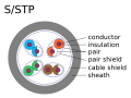
This section is not consistent and it needs cleanup. There are types explained in the figures, which are not explained anywhere the text, e.g. S/UTP. The table at the end is good! It shows that there are old an new names. These should be applied to the whole section (and the whole lemma). Please use only the old or only the new names (preferably the new of course!), but not a micture of old and new! -- 62.1.51.151 ( talk) 23:14, 17 January 2011 (UTC)
PDF's of unshielded twisted vs untwisted into 50 ohm - S11 plots
Same MIL 27500 wire, same lengths parallel vs. twisted to .3" twist length :
http://home.comcast.net/~ajawam4/tpair/untwisted-s11-50ohm.pdf
http://home.comcast.net/~ajawam4/tpair/twisted-s11-50ohm.pdf
http://home.comcast.net/~ajawam4/tpair/untwisted-s11-polar-50ohm.pdf
http://home.comcast.net/~ajawam4/tpair/twisted-s11-polar-50ohm.pdf
The polar plots are interesting, did this using a VNA with fixture cal:
http://home.comcast.net/~ajawam4/tpair/ref-s11-50ohm.pdf
...
Wamnet ( talk) —Preceding undated comment added 15:44, 20 March 2011 (UTC).
multiple reasons
There are three categories of reasons I've encountered.
Reason #1: Transformer effect. The ambient electromagnetic fields magnetically couple with thousands of very small twisted coils, instead of the entire untwisted "single-loop" signal-carrying wires (a transformer with a 1:10000000 ratio induces infinitely less noise than one with a 1:1 ratio; it's called lowering your effective loop area, ELA). This helps prevent the wires from playing the role of a transformer primary or secondary coil.
Reason #2: Self-cancelling twisted pairs. Each adjacent pair of twists consists of one oppositely-wrapped loop, so each pair is self-cancelling.
Reason #3: Half-twists exchange proximity to noise. On each half twist, the wire nearest to a noise-source is exchanged (copied from wikipedia article). Gary84 ( talk) 19:31, 26 November 2011 (UTC)
Images for the article
 |
 |
 |
 |
Hi I translated the images from the German article into english, please check wether I got that right before introducing into the article. -- Deelkar (talk) 01:13, 15 Jun 2005 (UTC)
- Looks good! "Mantle" should be "sheath", though.
- http://www.hifi.org.uk/tech/images/buc.gif - Omegatron 01:28, Jun 15, 2005 (UTC)
There are contradictions between the German and the English article concerning the nomenclature for STP, S/FTP and S/UTP. Especially because some manufacturers seem to call their cable STP while meaning S/UTP.-- Deelkar (talk) 02:26, 15 Jun 2005 (UTC)
- Are there any formal references that clearly says what is STP/ScTP/FTP, etc. Unlike in this article, this is how Cisco defines it:
- STP
- Screen around each pair and the whole shebang! (S/STP in this article) Note: STP is not the same as S/STP per TIA standards STP is IBM Type 1 cabling (not really used any more)
- FTP ; ScTP
- Synonyms. Outer foil or metal net, but no screen for individual pairs.
Note: TIA defines ScTP as Screened Twisted Pair having outer jacket shield the term FTP is not used any more here in the states
- UTP
- No shielding at all.-- itpastorn ( talk) 17:33, 2 March 2008 (UTC)
UTP diagram
I have just rolled back the UTP diagram which was replaced with an SVG as I don't think it is an improvement. The annotation is unreadable (even invisible) on the thumbnail as viewed in the article. Also the bicolour insulations are not clearly bounded as the original was. I am not sure I really understand this drive to eradicate png diagrams from Wikipedia, the displayed thumbnail is converted back to png anyway, but whatever, I'll go along with it, but the replacements need to be at least as good as what they are replacing. Also, it is one of a matching set of diagrams in this article and they should all be consistent. SpinningSpark 20:05, 24 December 2009 (UTC)
- I apoligise for that, i had attempted to re-raw it on my own using microsoft visio, yet it did not work properly. Pirmalry the tewxt did not convert properly i think awsthe big problem here. I am now working on replacing it with a directly converted SVG that will be identical to the source PNG file. From this point on the changes should be completely transparent to end users, If you have any further questions do not hesitate to contact me, thank you
| CompTIA A+ |
Koman90 (
Talk), A CompTIA A+ Certified IT Technitian |
- That was a lot better but the annotation on it is still not as clear as the original. It shows that it is raster text converted to svg paths. I have reverted it again. Please post any further attempts here for discussion before you put them in the article. I really don't see the point of all this trouble, the diagrams are perfectly ok as they are. SpinningSpark 00:31, 26 December 2009 (UTC)
You're right it's more trouble than it's worth, besides the SVG and PNG files are the smae amount of data after rendering and the png is already large enough to be understandable without being a strain on the servers. Thank you
- tired tracing the PNGs again to see if turning off the error suppression off helped any and the vector equivalent looks a little better. take a look.-- Koman90, A+ ( Verify) ( talk) 00:01, 27 January 2010 (UTC)
-
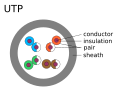 UTP cable
 -
 Shielded UTP cable
 -
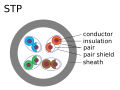 STP cable
 -
 Shielded STP cable


- I have redrawn all the images, and they seem to render fine, if you have any comments let me know. -- Svgalbertian ( talk) 05:33, 28 January 2010 (UTC)
| This page is an archive of past discussions. Do not edit the contents of this page. If you wish to start a new discussion or revive an old one, please do so on the current talk page. |
| This is an archive of past discussions. Do not edit the contents of this page. If you wish to start a new discussion or revive an old one, please do so on the current talk page. |
| Archive 1 | Archive 2 |
Untitled
Regarding unshielded twisted pair
If it ain't shielded, it'll short-circuit. So someone should correct this unprecise phrase, please. thanks, -- Abdull 12:08, 17 Mar 2005 (UTC)
- you mean insulated. electromagnetic shielding is different. - Omegatron
"f cancelling out electromagnetic interference kno"
- technically magnetic interference, right? only shielding cancels electric interference. - Omegatron 16:55, Apr 15, 2005 (UTC)
- Hmm.. effect of the magnetic field from one wire on the electrons from the other thus electromagnetic?? Mozzerati 19:42, 27 September 2005 (UTC)
- Well I don't think the method is efficient enough to cancel out direct magnetic interference, so the real thing it cancels out is crosstalk, which actually is EMI
- Well, actually, electric and magnetic fields are inseparable. You can't just have a magnetic field or just an electric field. They're orthogonally oriented components of each other. So both are probably canceled by the twisting.
When the wavelength is much longer than the wire length they are pretty much separate, and when it is much longer than the wire spacing they can still be treated separately.
Consider the electromagnetic field due to a nearby radio station. The induced voltage will be pretty much the same on both wires, called common-mode. That won't get through the transformer at the end.
Consider a 50Hz or 60Hz magnetic field from a nearby power cable. An untwisted cable looks like a very long and narrow wire loop, and a changing magnetic field will induce a current. Twisting with a pitch somewhat less than the wavelength causes the induced currents to change sign every half twist.
Consider two twisted pairs in the same cable. If the twist pitch is about equal, both inductive (magnetic) and capacitive (electrostatic) coupling can add over the length of the cable. (Model capacitive coupling as capacitors between the wires, larger capacitors for closer wires.) With different twist pitch, the induced current and voltage cancels over lengths somewhat longer than the shorter twist pitch.
Gah4 23:25, 22 June 2007 (UTC)
need of help
This page may need the expertise of a professional Akupta321 06:31, 18 March 2006 (UTC)
Merge stubs into this article
I have already gone ahead and merged the shielded twisted pair stub into this article. I would also like to do so with the unshielded twisted pair article. Before I do so, I'd like some other people's opinions. N. Harmon 01:35, 28 May 2006 (UTC)
I think the foiled twisted pair article should be merged into here also. N. Harmon 01:43, 28 May 2006 (UTC)
I also think we should consider merging several cable category articles into this one. N. Harmon 02:22, 28 May 2006 (UTC)
- Oppose the merger of cable category articles, but support the merger of the twisted pair variants. The cable category articles are (from what I can tell) pretty good, this article shouldn't concern itself with them. By the way, from the history I noticed that the user Mozzerati originally seperated the sections, see what he has to say. Also, take a look at all the articles pointing here and see if it is possible to improve that. In my opinion this article is in need of some serious attention, I'll help around where I can. -- Bruce 09:54, 28 May 2006 (UTC)
- Two of the cable category articles are good, specifically Category 5 cable and Category 6 cable. However they do seem to repeat a lot of information that is really about twisted pair cables and not necessarily THAT category of cable. I appreciate your thoughts on this. N. Harmon 15:37, 28 May 2006 (UTC)
- Oppose keep specialized info in seperate articles. Generic info might be merged into twisted pair. Bemoeial 12:48, 6 June 2006 (UTC)
"'oppose'" - There are hundreds of type of twisted pair cables, but "Category X" is not a generic term, it is a specific term for this particular cable. It deserves a place of it's own. Trane Engineer
"'oppose'" The information for Cat 6 cable was good, and should be in its own catagory. <pun> I would not look it up under twisted pair, I would search under Category X. Twisted pair is too general, like putting it all under "wire". 69.31.216.194 17:48, 6 June 2006 (UTC) Tom Moffatt
"'Oppose" It does take some knowledge of most types of media cable to differenciate twisted pair. It can't just be classified to just Cat5 cables! ~ T. Hansen, California
- Oppose Too much info to merge, Wikipedia is not paper. Themindset 16:15, 9 June 2006 (UTC)
- gently oppose there's a real need for a discussion of the physics, grounding characteristics etc. of the different types. I started to think about writing it, but got sidetracked. I think they are sufficiently important and different to be worthy of separate articles. On the other hand, there's nothing wrong with merging for some time and then later splitting again. Mozzerati 20:31, 9 June 2006 (UTC)
Cancelation between pairs
To me it is not obviously why two pairs in the same cable does not crosstalk a lot. It looks like they are two coils on the same transformer. I expect that they are twisted at the same rate. Appearently this is not the case and I think this article should explain why. 62.79.30.244 08:23, 12 February 2007 (UTC)
- "Why does each pair in Cat 5/5E/6 cable have different twist rates?" [1]
- "EIA-568 ... Pair Assembly: The pair twists of any pair shall not be exactly the same as any other pair. The pair twist lengths shall be selected by the manufacturer to assure compliance with the crosstalk requirements of this standard." [2]
- "... within the Cat 5 cable. Each individual phone line ... each phone line (made of two twisted strands of copper) has a "twist rate" different from the other three lines. One of the four pairs will have a high number of twists per inch, one will have a low number of twists per inch, and the other two will have twist rates somewhere in between. That difference in twist rates prevents signals from bleeding across phone lines." [3]
- "UTP (Unshielded Twisted Pair) cable rated as Category-5 typically contain (8 conductors) 4 pairs of 24 awg solid copper wire. Each of the pairs is two conductors twisted together, and each pair in a cable has a different number of twists per inch when compared to the other pairs." [4]
- "CAT5/5e/6 cables consist of four pairs of cables... the slight difference in twist rate for each pair... " [5]
- twist rate pedantry [6]
-- 76.209.28.72 18:34, 5 June 2007 (UTC)
- To simplify what the anon above has stated: Take a spare cable that you have, and remove the shielding; notice how each of the four pairs is twisted differently, with each pair having a different number of twists? Since the rate of twists for each pair is different, crosstalk (the aforementioned "bleeding") is less likely to occur. PeanutCheeseBar 19:24, 14 June 2007 (UTC)
differential vs balanced
I'm just trying to clear up misconceptions around the 'pedia about EMI and cables. As I understand it:
- "Balanced" refers to keeping the source and load impedances of a transmission line equal, so that any noise that couples into the wires will couple equally, and can be rejected at the other end.
- Twisting cancels out fields that couple into adjacent twists.
- "Differential" refers to sending signals of opposite polarity down the wires. This is so that the wire's EM fields mostly cancel out.
- Shielding does a variety of things
— Omegatron 16:05, 31 May 2007 (UTC)
Balanced and differential are essentially the same. Keeping the source and load impedance the same is matched, usually impedance matched.
Balanced means the currents (and for uniform impedance, the voltage) are equal and opposite in the two wires. Both electric and magnetic fields fall off fairly fast with distance
Yes, it is really the electromagentic field, but one can separately consider capacitive coupling (due to the electric field) and inductive coupling (due to the magnetic field). Two parallel UTP cables with the same twist pitch will have both capacitive and inductive coupling as the fields add up over the length of the cable. With different twist pitch, in the long run the coupling, both inductive and capacitive coupling average out to zero.
Note that impedance matching is not required for UTP operation. Assuming transformers are used on both ends, the reflected signal will still be balanced.
Gah4 Gah4
- Yes, matching source and load impedances is another important feature, to prevent reflections and "ringing".
- "Balanced" applies to the impedances of each line, though, not the currents or the signal. It means that both lines are driven by the same source impedance and terminated by the same load impedance (and have the same characteristic impedance?), so that any noise that couples into them will be equal in both and can be rejected. — Omegatron 23:32, 22 June 2007 (UTC)
A reference to balanced is probably applicable. It looks pretty good, but is mostly meant for low frequency (audio) applications. UTP works just find if the impedances are wrong, as long as they aren't too far off. If transformer driven, the currents will be equal and opposite, which is most important as far as EMI (radiation) is concerned. Equal impedance to ground is important, but is reasonably likely in a twisted pair cable.
Note that telephone wiring uses 600 ohm source/load but the UTP cable has much lower impedance. Yes, the impedance for each wire to ground must be (approximately) equal, but that is fairly unrelated to the cable impedance. If the impedances to ground are different then equal voltage/current in won't stay equal.
Gah4 08:08, 10 September 2007 (UTC)
I added the Historical Note, forgot to enter Edit Summary. LoopTel 19:23, 5 July 2007 (UTC)
Disagreement between advantages/disadvantages
First we say that "It is a thin, flexible cable that is easy to string between walls." Then we say that "...twisted pair cables usually have stringent requirements for maximum pulling tension as well as minimum bend radius. This relative fragility of twisted pair cables makes the installation practices an important part of ensuring the cable’s performance." Which is it? — BRIAN 0918 • 2007-09-12 15:11Z
Mains twisted pair
The article appears to have not noticed that there is also twisted pair flex that has nothing to do with data transmission, and is twisted solely because its the lowest cost way to keep 2 insulated conductors together. Such flex was in widespread use in the first world until the 1960s as mains flex, and is still sometimes found in poorer countries. Tabby ( talk) 12:13, 1 March 2008 (UTC)
Why UTP
"Unshielded twisted pair (UTP) cabling, because of its 100-year history of use by telephone systems, both indoors and out, is also the most common cable used in computer networking."
no, because its the cheapest thing that does the job. Thats more or less always the reason for such decisions. Tabby ( talk) 12:13, 1 March 2008 (UTC)
by ( http://tldp.org/HOWTO/Serial-HOWTO-5.html#ss5.2) twisted pair technology obtains higher speed Vy0123 ( talk) 04:18, 19 March 2008 (UTC)
- Compared to the serial port - does not mean much! Tabby has already said all there is to say about this subject.-- itpastorn ( talk) 09:26, 19 March 2008 (UTC)
Tabby refers to price. The tdlp refers to the principle of twisted pair technology in writing:-
All of the EIA-232 serial cable wires use a common ground return wire so that twisted-pair technology (needed for high speeds) can't be used without additional hardware.
It is somewhat tragic that the RS-232 standard from 1969 did not use twisted pair technology which could operate about a hundred times faster. Twisted pairs have been used in telephone cables since the late 1800's. In 1888 (over 115 years ago) the "Cable Conference" reported its support of twisted-pair (for telephone systems) and pointed out its advantages. But over 80 years after this approval by the "Cable Conference", RS-232 failed to utilize it.
RS-232 was mostly for connecting modems to computers, usually over a short distance. It was later that the idea of using it for longer distances came along. RS-232 also has current limited drivers, also not so good for longer distances. Gah4 ( talk) 02:04, 30 October 2008 (UTC)
Is it possible that the value of the principle of twisted pair technology can lead to enduring use and ubiquity and, in the process, economies of scale in production draw down the price of utp cabling? Vy0123 ( talk) 11:27, 19 March 2008 (UTC)
This needs dumbing-down to make it more accessible
I read this article because I have read that twisted pairs are a modern alternative to coaxial cable for data transmission on local networks. Specifically, I wanted to understand what goes on in the "pairs". I couldn't get my answer from the article - it assumes I already know the answer. "two conductors are wound together for the purposes of canceling out electromagnetic interference (EMI) from external sources... In balanced pair operation, the two wires typically carry equal and opposite signals (differential mode) which are combined by addition at the destination". Are the two wires in each pair the quivalent of the two wires that provide the circuit powering a light bulb or other device ? Do data lines require 2 wires the same way power lines do ? What does it mean, and how does it happen, that the two wires in a pair carry equal and opposite signals ? Is a single twisted pair equivalent to a coaxial cable ? Or does each twisted pair provide a single electric wire, and two twisted pairs are required to provide a complete circuit ? Please consider making the article comprehensible to the intelligent reader who knows nothing about the subject. Rcbutcher ( talk) 18:10, 22 May 2008 (UTC)
- Excellent observation! To answer your main question: A twisted pair is two halves of one circuit. Hopefully, my quick addition to the lead will help start the simplifying process. (Rather than "dumbing down" which sounds like removal of difficult material, I prefer to think that the article will be expanded downward to include readers who are beginners to the topic.)
Binksternet (
talk)
01:09, 23 May 2008 (UTC)
- Sounds good. Indeed, what I meant was not to remove difficult material but to make it more accessible to the mentally active reader who knows very little about the subject but wants to get a basic accurate understanding of it, in this case how the wires going from his PC's LAN card to the hub or cable modem work. Rcbutcher ( talk) 14:33, 23 May 2008 (UTC)
In a coax cable, the shield does a very good job of keeping the signals inside and interference outside. UTP doesn't have a shield to keep the signal from radiating like an antenna. So, yes, the two wires work the same way that the two wires on a power line work. A twisted pair works pretty much like one coax cable, though not quite in the context of ethernet. Because of the way collision detection works on ethernet, it takes two pairs for UTP ethernet, but only one coax cable for coaxial ethernet. Gah4 ( talk) 10:21, 23 October 2008 (UTC)
Understanding electromagnetic interference is hard without understanding electromagnetic induction, and that isn't easy (even for physics students). Maybe, though, the effects of twisting can be explained statistically. One statistical technique is called round to even. When rounding decimal numbers ending in five, such that rounding either up or down would generate the same rounding error, one rounds such that the last digit is even. On the average, this results in rounding up and down at about the same rate, such that the bias is removed. Two electromagnetic signals can couple if there is even a small bias, such as one wire of the pair being closer to the interference source than the other. Twisting causes, on average, most interference to cancel out. Gah4 ( talk) 20:16, 10 November 2008 (UTC)
Loaded line
I have a real problem with this explanation of loading,
- Loaded twisted pair: A twisted pair that has intentionally added inductance. Wires that go long distances and are terminated at higher than the characteristic impedance usually have load coils to increase their inductance, unless they are to carry higher than voiceband frequencies. (A transmission line with lower impedance than it source and load has extra capacitance, resulting in a dropoff at higher frequencies. Loading coils balance out the excess capacitance for wavelengths somewhat longer than the coil spacing. At shorter wavelengths the frequency response dropoff is increased.)
The compensation that loading achieves has nothing to do with the terminations of the line. The distortion resulting on the line is the same irrespective of load. There is not suddenly too much capacitance because the terminations increase in impedance. The inductance required to meet the Heaviside condition is exactly the same no matter what the load. It is true that reducing the termination impedance of a line can improve frequency response, but this is an entirely different effect, unrelated to loading. It is so much at odds with the standard analysis of loading that I think a reference to a text using it is required before it can stay. However, I will hold off reverting it to give the editor who put it in a chance to reply. In any case, the detailed description of loading belongs in the loading coil article. All that is needed here is a brief, one line description of what loading is. SpinningSpark 20:21, 23 October 2008 (UTC)
Cable Shielding
Article says that the shielding material must be grounded for shielding to work. Granted its standard practice on a most types of twisted pair installs to ground the shielding material but i dont' think it materially impacts the shielding...I thought the shielding was based on Gauss's law that the shielding creates a Gaussian Cage... Grounding the shielding prevents EMF interference/crosstalk how exactly?
- An ungrounded shield is far worse than having no shield at all. The unconnected shield acts as a passive antenna re-rediating any signal that is induced into it. SpinningSpark 08:26, 23 April 2010 (UTC)
The idea of cable shielding is to create a linear faraday cage (see http://en.wikipedia.org/wiki/Faraday_cage). As long as any gaps don't exceed wavelength of the signal (signals) within the cable it will not radiate outward. Once you have a gap that the wavelength can exit (not tied to ground) the emission will radiate outward. The wavefront will also wrap around to the other side of the shielding for a distance based on the wavelength of the signal. The source of the emission you are concerned with could be either from within the cable or within environment. In most cases you are concerned on what is coming from within the cable DanO256 ( talk) 23:44, 15 April 2011 (UTC)
Not correctly grounding the cable shielding (and equipment) can also cause equipment damage as well as be a shock hazard (ouch!) DanO256 ( talk) 23:44, 15 April 2011 (UTC)
We should refer to the TIA and ISO standards as well as groups who propagate the knowledge of proper cabling practices based on the TIA & ISO standards. As an example: BICSI ( https://www.bicsi.org) DanO256 ( talk) 23:44, 15 April 2011 (UTC)
TIA-607 GROUNDING AND BONDING REQUIREMENTS FOR TELECOMMUNICATIONS DanO256 ( talk) 23:44, 15 April 2011 (UTC)
Category 8 cable ?
Seems like there's a new Cat 8 cable http://hiddenwires.co.uk/resourcesarticles2005/articles20050905-03.html 84.134.124.60 ( talk) 15:41, 20 June 2010 (UTC)
Low end cable problem
I see that someone's tagged the section "Low end cable problem" as being US-focussed. I agree, but rather than fix that the whole section seems of dubious notability. It appears to be based on a single report which is not even cited. The section seems overly long for that single report. Similar comments apply to the following section (Copper clad aluminium). I am not disputing the accuracy of the material but the coverage seems disproportionate.
Compare with the article on Rolex which has a single sentence on forgeries, and the problem of cheap copies is obviously much more prevalent in that kind of area than here. We don't see comments that fakes may not keep the correct time, or that the wrong oil may have been used to lubricate the watch.
It appears to me that we could trim those sections in their entirety without harming the article in the slightest. CrispMuncher ( talk) 22:41, 20 November 2009 (UTC)
- Yeah, i agree. I think the section has undue weight, and could be trimmed considerably. Probably the low-quality cable problem does exist, but it seems it would be present in any commodity product market (AA batteries, plywood, wrenches). I don't think there is a serious problem where no one in the US can get a properly manufactured cable from a reputable manufacturer. I suggest you make the edits you have proposed. I could review your changes and make and suggestions or changes. Cheers! — fudoreaper ( talk) 06:45, 24 November 2009 (UTC)
This section was originally in the Category 5 article. I've moved the section and the discussion here. -- Kvng ( talk) 15:29, 3 July 2010 (UTC)
- I think this is of dubious relevance here. This article is about twisted pair, not the fire safety of cables. This is mostly an issue of the materials the jacket, and to some extent the core insulation, is made from. This has nothing to do with twisted pair construction or purpose. The report referenced is about communications cables in builing infrastructure. This is exactly what CAT5 and CAT6 cables are (this is where the material has been moved from) so it has been moved from an article with only marginal relevance to an article where it has no relevance. Although the material is tagged as being US-centric, there are similar regulations in Europe and cables which meet these standards are known as LFH and LS0H (or LSH) depending on standard. These are standards that apply to all sorts of cables, including electric power, not just comms cables, and certainly not just twisted pair.
- Likewise the material on cable manufacturing is largely about the insulation and jacketing. The sentence or two on twisting would be entirely baffling to anyone who does not already know how the twisting is done. All the rest could be said to be either cable in general, or CAT5/6 specific. Either way it should be deleted en-bloc from this article and either moved back to CAT5/6 or to the cable article. SpinningSpark 18:16, 3 July 2010 (UTC)
- I agree that Cable would have been a better landing place for this. There's a Fire protection section there. I'd go ahead and move it were it not for growing number of negative comments about the material. I'm fine to let it die here. -- Kvng ( talk) 05:06, 4 July 2010 (UTC)
SF-UTP type
Just noticed it today my dad bought a new cable he needed and he bought this type i didn't seen before , it's in center europe so anyone's guess who made it , it says on the cable digitus web page and IEC/ISO and TIA/EIA standards —Preceding unsigned comment added by Xowets ( talk • contribs) 16:03, 21 August 2010 (UTC)
why can't we use parellel pair of wires instead of twisted pair in guided transmission media??
 because it will act like anttenae  —Preceding
unsigned comment added by
122.161.12.62 (
talk)
18:28, 20 September 2010 (UTC)
Please explain something about the twisted pairs.
"two conductors (the forward and return conductors of a single circuit) are twisted together for the purposes of canceling out electromagnetic interference" But as far as I know the first and second wire are for send or receive and the 3 and 6 wire is vice versa send/receive. My problem of understanding the quote is this: if 1 and 2 wires (let's say white/orange and orange are for the sending signal why in the quote it says forward and return conductor are twisted? Isn't the send signal simply being transmitted with the two wires twisted? So there are two forward and two return conductors and the forward/return conductors are seperated and NOT twisted each other. Orange for receiving and greens for sending for example. I know I made too complicated my confusion :D-- Leonardo Da Vinci ( talk) 13:23, 30 November 2010 (UTC)
- No, the cancellation of external fields only works if you use a pair for each signal so that signal currents flow in opposite directions on the two conductors. That's the point. If you split the pairs, and run the two conductors of one signal in two different pairs, you get no cancellation; this is a pretty common wiring error in Ethernet cables and cable tester instruments will detect and alert for this condition. -- Wtshymanski ( talk) 15:09, 30 November 2010 (UTC)
- The sending pair is a circuit carrying alternating or pulsing electrical energy. The signal goes out on both wires of the twisted pair at the same time. It's the fact that a circuit is required that makes the twisted pair work. If energy could be thrown down one conductor (with no circuit established) then the twisted business would not have any effect. Likewise, the receiving pair is a circuit. Hope that helps! Binksternet ( talk) 15:31, 30 November 2010 (UTC)
So the sending signal (white+orange wires in scheme 578B) TX+ and (pure orange wire) TX- represents the two polarities of the current? The sending signal is TX+(white+orange) with a positive to negative current TX-(pure orange) and the second wire is TX- where the second conductor is receiving the current in opposite direction to the other end of the UTP cable where TX+ is located? I tough the sending wires TX+ and TX- where only in one direction. But now I think I get it :). You've spoken about cable tester instruments. Well I have an interesting question about you :). Once I've reversed the orange/white and orange wires and the cable tester showed a red flash in 1&2 wires, yet the internet was working. Not only this but it did NOT worked with the normal wire placement. Why is this? -- Leonardo Da Vinci ( talk) 15:34, 30 November 2010 (UTC)
- My understanding of a twisted pair is that an external source of electrical noise may induce a voltage between the two wires due to the small noise field passing between the wires. However, it is likely (with tight twisting) that the field will have almost the same effect a short distance away in the cable, where the wires are twisted to the other side, so the second induced voltage will cancel the first.
- All sorts of issues can make a cable fail. Perhaps the first connection in fact had a bad joint, and when it was redone (with the wrong wiring) the connections were properly made. If there is no nearby active noise source, incorrect connections probably won't matter much. Johnuniq ( talk) 04:13, 1 December 2010 (UTC)
Cable shielding cleanup
This section is not consistent and it needs cleanup. There are types explained in the figures, which are not explained anywhere the text, e.g. S/UTP. The table at the end is good! It shows that there are old an new names. These should be applied to the whole section (and the whole lemma). Please use only the old or only the new names (preferably the new of course!), but not a micture of old and new! -- 62.1.51.151 ( talk) 23:14, 17 January 2011 (UTC)
PDF's of unshielded twisted vs untwisted into 50 ohm - S11 plots
Same MIL 27500 wire, same lengths parallel vs. twisted to .3" twist length :
http://home.comcast.net/~ajawam4/tpair/untwisted-s11-50ohm.pdf
http://home.comcast.net/~ajawam4/tpair/twisted-s11-50ohm.pdf
http://home.comcast.net/~ajawam4/tpair/untwisted-s11-polar-50ohm.pdf
http://home.comcast.net/~ajawam4/tpair/twisted-s11-polar-50ohm.pdf
The polar plots are interesting, did this using a VNA with fixture cal:
http://home.comcast.net/~ajawam4/tpair/ref-s11-50ohm.pdf
...
Wamnet ( talk) —Preceding undated comment added 15:44, 20 March 2011 (UTC).
multiple reasons
There are three categories of reasons I've encountered.
Reason #1: Transformer effect. The ambient electromagnetic fields magnetically couple with thousands of very small twisted coils, instead of the entire untwisted "single-loop" signal-carrying wires (a transformer with a 1:10000000 ratio induces infinitely less noise than one with a 1:1 ratio; it's called lowering your effective loop area, ELA). This helps prevent the wires from playing the role of a transformer primary or secondary coil.
Reason #2: Self-cancelling twisted pairs. Each adjacent pair of twists consists of one oppositely-wrapped loop, so each pair is self-cancelling.
Reason #3: Half-twists exchange proximity to noise. On each half twist, the wire nearest to a noise-source is exchanged (copied from wikipedia article). Gary84 ( talk) 19:31, 26 November 2011 (UTC)
Images for the article
|
|
|
|
Hi I translated the images from the German article into english, please check wether I got that right before introducing into the article. -- Deelkar (talk) 01:13, 15 Jun 2005 (UTC)
- Looks good! "Mantle" should be "sheath", though.
- http://www.hifi.org.uk/tech/images/buc.gif - Omegatron 01:28, Jun 15, 2005 (UTC)
There are contradictions between the German and the English article concerning the nomenclature for STP, S/FTP and S/UTP. Especially because some manufacturers seem to call their cable STP while meaning S/UTP.-- Deelkar (talk) 02:26, 15 Jun 2005 (UTC)
- Are there any formal references that clearly says what is STP/ScTP/FTP, etc. Unlike in this article, this is how Cisco defines it:
- STP
- Screen around each pair and the whole shebang! (S/STP in this article) Note: STP is not the same as S/STP per TIA standards STP is IBM Type 1 cabling (not really used any more)
- FTP ; ScTP
- Synonyms. Outer foil or metal net, but no screen for individual pairs.
Note: TIA defines ScTP as Screened Twisted Pair having outer jacket shield the term FTP is not used any more here in the states
- UTP
- No shielding at all.-- itpastorn ( talk) 17:33, 2 March 2008 (UTC)
UTP diagram
I have just rolled back the UTP diagram which was replaced with an SVG as I don't think it is an improvement. The annotation is unreadable (even invisible) on the thumbnail as viewed in the article. Also the bicolour insulations are not clearly bounded as the original was. I am not sure I really understand this drive to eradicate png diagrams from Wikipedia, the displayed thumbnail is converted back to png anyway, but whatever, I'll go along with it, but the replacements need to be at least as good as what they are replacing. Also, it is one of a matching set of diagrams in this article and they should all be consistent. SpinningSpark 20:05, 24 December 2009 (UTC)
- I apoligise for that, i had attempted to re-raw it on my own using microsoft visio, yet it did not work properly. Pirmalry the tewxt did not convert properly i think awsthe big problem here. I am now working on replacing it with a directly converted SVG that will be identical to the source PNG file. From this point on the changes should be completely transparent to end users, If you have any further questions do not hesitate to contact me, thank you
| CompTIA A+ |
Koman90 (
Talk), A CompTIA A+ Certified IT Technitian |
- That was a lot better but the annotation on it is still not as clear as the original. It shows that it is raster text converted to svg paths. I have reverted it again. Please post any further attempts here for discussion before you put them in the article. I really don't see the point of all this trouble, the diagrams are perfectly ok as they are. SpinningSpark 00:31, 26 December 2009 (UTC)
You're right it's more trouble than it's worth, besides the SVG and PNG files are the smae amount of data after rendering and the png is already large enough to be understandable without being a strain on the servers. Thank you
- tired tracing the PNGs again to see if turning off the error suppression off helped any and the vector equivalent looks a little better. take a look.-- Koman90, A+ ( Verify) ( talk) 00:01, 27 January 2010 (UTC)
-
UTP cable
-
Shielded UTP cable
-
STP cable
-
Shielded STP cable
- I have redrawn all the images, and they seem to render fine, if you have any comments let me know. -- Svgalbertian ( talk) 05:33, 28 January 2010 (UTC)
| This page is an archive of past discussions. Do not edit the contents of this page. If you wish to start a new discussion or revive an old one, please do so on the current talk page. |