|
| This article is rated B-class on Wikipedia's
content assessment scale. It is of interest to the following WikiProjects: | ||||||||||
| |||||||||||

Stuff copied here from op-amp page in preparation.
Op-amps have applications as artificial neurons in neural nets. Specifically, as a number of summer amplifiers attached to a central amplifier attached to a comparator or schmitt trigger. For details, see http://www.rgu.ac.uk/files/chapter10%20-%20implementing%20ANNs.pdf
The correct term for this cct is Ideal Diode. The term super suggests something thats actually better than a diode. This term super diode is not used in electronics (not that Ive heard of) and should therfore be changed to ideal diode.-- Light current 17:44, 29 September 2005 (UTC)
- It is actually better than a diode. :-)
- I've seen the terms "super diode" and "precision diode" and simply "precision half-wave rectifier". The latter is the most accurate. I haven't seen it called an "ideal diode". (Oh wait. Here is one example.)
- [1] [2]
- This should be at Talk:Super diode, anyway. — Omegatron 19:26, 29 September 2005 (UTC)
- the ideal diode, as the name says, is something ideal that does not actually exist: it has a threshold of 0V and can bare tensions up to without letting any current pass through. The super diode has a behaviour that is very similar to the ideal one, but it's threshold is about (that is small, but not zero), and the range of voltages it can bare is not unlimited. Alessio Damato 15:22, 7 October 2005 (UTC)


- Exactly. I think "precision rectifier" is a "less slangy" term. — Omegatron 18:24, 7 October 2005 (UTC)
CAn we change it then to precision rectifier?-- Light current 19:36, 7 October 2005 (UTC)
Yes it is better than a diode. Its ideal but not super-- which would imply-- well Im not sure what it implies. I should have said better somehow than an Ideal diode. The term super as applied to electronics/electrical engineering (apart from superconductor) is outside my professional experience - Light current 22:11, 29 September 2005 (UTC)
THis statement seems to convey very little useful info. I think its wrong anyway. I will delete unless it can be tightened up-- Light current 01:15, 30 September 2005 (UTC)
Expunged useless stuff-- Light current 18:05, 12 October 2005 (UTC)
Addition: Whereas Input-Bias Current is more or less independent from the input voltage difference, it depends on temperature. Neither is output current dependent on the output voltage, as long as the opamp is capable do deliver that current. Therefor, in- and output-impedance are missleading terms in this context; impedance is used to discribe current variation caused by voltage change. This ratio is neither constant for in- nor outputs of opamps. — Preceding unsigned comment added by 83.65.147.83 ( talk) 20:36, 20 November 2012 (UTC)
Generally, we want to cover opamp circuits the way they are used, not as variations of a universal configuration, so I'm not sure these recent edits are that helpful. Maybe you could put something like that in the differential amplifier article, showing the connection between diff amps and all the other varieties? (I did the same thing with a "universal transistor amplifier", and it's not a great idea. See Talk:Common collector, for example.)
Although the use of HTML to represent math in articles is somewhat contentious, using complicated HTML to simulate the same effect as TeX is definitely bad, and mixing both within the same equation is very bad. Can you restore them to TeX? — Omegatron 04:16, 2 November 2005 (UTC)
- I edited the op amp page because the edit would have helped me in my ECE class if it were there when I first looked it up. You said that "Generally, we want to cover opamp circuits the way they are used" - however obviously we can't go through every permutation of an op amp circuit - we need general cases to consolidate knowlege into learnable peices. I rearranged the page because it showed very clearly that some circuits were special cases of the differential circuit. So not only does it show the special cases now, but it shows where the special cases come from more clearly than before. My goal for this page is to display a even more general op amp circuit so that you can use one equation for any op amp circuit consisting of resistors and power supplys. Fresheneesz 23:14, 8 November 2005 (UTC)
- So I guess it depends on what our goal for this article is. Is it a teaching tool or a reference?
- I doubt it's a great teaching tool, anyway. The problem with using a "universal amplifier" to teach all the various permutations is that the student won't recognize the permutations when they see them later. I was taught transistor amplifiers by saying that all the various types were variants on a universal transistor amplifier and I didn't learn them that well. I tried to add this to the various articles like common collector and it was (rightly) removed. I'm not sure this is a great idea.
- We should probably just show both renditions of the same circuits, or maybe move the universal diff amp stuff to the differential amp article, and leave this one as a reference. —
Omegatron 15:42, 9 November 2005 (UTC)
- Well, I see what you're saying. And I do take wikipedia to be a reference not a "learning tool" - despite the fact that you can learn a huge amount from reading reference material. The thing is, here, the article still keeps all the diagrams of - and explanation for - the circuits that were previously displayed as stand alone circuits. However it adds the element of some being permutations of others. So students using wikipedia to learn about op amps will see not only the specific differences between non-inverting, inverting, and differencing amplification circuits, but can also generalize the equations and be able to more easily remember how an op amp works. In my experience, I've found that one hard-to-learn equation beats out learning many small equations - you'll always be doing more work learning the many small equations. I think adding the permutations to the differencing amplifier page would be much more obscure - I know I wouldn't look for equations about an inverting amplifier in the differencing amplifer page.
Fresheneesz 02:47, 10 November 2005 (UTC)
- But all of these circuits are permutations of each other. It's just a matter of perspective. You say that the inverting amp is a simplification of the differential amp; I say that the differential amp is a combination of a voltage divider and an inverting amp. Which of us is right?
- I'm going to remove those bits and leave it the way it was before; categorized by topology only. (So the only simplifications of the differential amp are the ones that have certain resistor values, but still the same layout.) — Omegatron 16:11, 21 February 2006 (UTC)
- Well, I see what you're saying. And I do take wikipedia to be a reference not a "learning tool" - despite the fact that you can learn a huge amount from reading reference material. The thing is, here, the article still keeps all the diagrams of - and explanation for - the circuits that were previously displayed as stand alone circuits. However it adds the element of some being permutations of others. So students using wikipedia to learn about op amps will see not only the specific differences between non-inverting, inverting, and differencing amplification circuits, but can also generalize the equations and be able to more easily remember how an op amp works. In my experience, I've found that one hard-to-learn equation beats out learning many small equations - you'll always be doing more work learning the many small equations. I think adding the permutations to the differencing amplifier page would be much more obscure - I know I wouldn't look for equations about an inverting amplifier in the differencing amplifer page.
Fresheneesz 02:47, 10 November 2005 (UTC)
In some other encyclopedias this material is splitted into several articles. To generate cross-language links, the header references are used (for instance, . Please avoid changing the headers without the real need. Audriusa 20:38, 2 January 2006 (UTC)
en:Operational amplifier applications#Differentiator
- Alternatively, feel free to change the section titles, just put an {{ anchor}} to the old name in the same place. — TedPavlic ( talk/ contrib/ @) 14:17, 6 January 2010 (UTC)
We should include Breakpoint generators here.-- HappyEater 16:40, 19 May 2007 (UTC)
In the explanation for the non-inverting amp, the resistor subscripts don't correspond to the picture. "A third resistor, of value R_\mathrm{f} \| R_\mathrm{in}, added between the Vin source and the non-inverting input, while not necessary, minimizes errors due to input bias currents."
I looked everywhere for what the contributor meant by "R1||R2" and couldn't find any references besides: 'parallel-to' in geometry; and a logical OR operator in C programming. I don't think it means either of those and might possibly be a typo for "R1/R2". This needs to be verified by someone with more knowledge than myself.
- The symbol means "impedance of the parallel combination of". That is, . I've updated the document in the case you're talking about (for the inverting amplifier). I've also clarified the issues involving bias currents and input impedance. Some of the new comments there apply equally as well to any of the other OA circuits. — TedPavlic | ( talk) 21:03, 19 November 2008 (UTC)

I have often noticed a tendency to confusion around this term. I believe the usage is to call this circuit with an opamp and two matched pairs of resistors, a "Difference Amplifier". "Differential Amplifier" is the term used to name the input stage inside the opamp, as you will see if you follow the link to that article. Friendly Person ( talk) 13:31, 19 June 2008 (UTC)
If a fig is not provided for the "Zero level detector" "section", the section should be removed. — TedPavlic ( talk) 14:35, 26 January 2009 (UTC)
The diagram for this is incorrect. One of the input buffer amplifiers has the '+' and '-' inputs transposed. 20.133.0.13 ( talk) 13:37, 17 February 2009 (UTC)
Sorry, I have removed the link to the page about Philbrick absolutely involuntarily. I have no idea how it has happened and I was unpleasantly surprised when I saw Zen-in's remark. Philbrick is a legend; I highly appreciate his achievements. Circuit-fantasist ( talk) 15:35, 20 March 2009 (UTC)
There is currently a page dedicated to the inverting amplifier configuration of the op amp. The page doesn't seem to add much value beyond what is already in Operational amplifier applications or Operational amplifier. Merge? Scottr9 ( talk) 14:41, 23 April 2009 (UTC)
- I'd say so. Noodle snacks ( talk) 08:31, 27 April 2009 (UTC)
- Not all inverting amplifiers involve operational amplifiers, so there could be a case for a separate page for them, BUT the existing page is not it, as it stands (because it assumes opamps). I think there should be a bit of mention of inverting and non-inverting amplifiers in general terms in the amplifier article, as well as some discussion somewhere of the relevance of inverting amplifiers to absolute phase and the idea that an even number of inverting stages tending to have lower distortion. Maitchy ( talk) 05:33, 4 May 2009 (UTC)
There is an orphaned Log_amplifier page. The quality of that page is awful, but I would suggest actually keeping it and merging it with the Logarithmic Output from this page (and hopefully improving the content of the log amp page!).
Thus, Logarithmic output would have it's own main page and the section in this page could be excerpted from that article. This would be similar to how the Operational_amplifier_applications#Precision_rectifier section is handled with the Precision_rectifier main page.
Furthermore, something should be done to connect the Logarithmic_video_amplifier page.
Marangu ( talk) 13:21, 21 May 2009 (UTC)
The text on power supply design contained some very odd wording that I regard as meaningless. I have edited to remove the offending text, but if anyone can supply a meaningful alternative then please insert. —Preceding unsigned comment added by 86.53.81.124 ( talk) 16:52, 28 December 2009 (UTC)
- Restored from your edit and tried to add some clarity. You can find an example circuit that uses current on the OA rails as an input to an external amplifier in Horowitz and Hill. In particular, look at the notable examples (the gray section) at the end of the operational amplifier section. There is a high gain amplifier there (provided without explanation) that matches the text I've inserted. — TedPavlic ( talk/ contrib/ @) 06:02, 29 December 2009 (UTC)
The role of the op-amp in this circuit is to compensate the voltage drop across the capacitor. For this purpose, the op-amp adds so much voltage to the input voltage as it loses across the capacitor. The properly supplied op-amp acts as a compensating voltage source connected in series to the capacitor and the input voltage source.
This idea may be generalized for all the op-amp inverting circuits with parallel negative feedback (e.g., Inverting amplifier, Summing amplifier, Differentiator, Logarithmic output, Exponential output from this page). In all these circuits the op-amp compensates the voltage drop across the element connected between the output and the inverting input by adding the same voltage to the input voltage as it loses across this element. See also Voltage Compensation. Circuit dreamer ( talk) 18:38, 30 March 2010 (UTC)
- Two reasons why this has been removed:
- This is a non-standard explanation (whilst it's true, I've never seen it described like this).
- Even if it were true, it applies to all negative-feedback topologies, so it's unnecessary to add this detail to purely the integrator and differentiator.
- Oli Filth( talk| contribs) 10:46, 31 March 2010 (UTC)
- The page. Let's first see what happens if someone curious web reader wants to understand what an op-amp integrator is. Of course, he/she will write "op-amp integrator" in the Google window and will see this Wikipedia page at the first place from all these 100000 pages. The visitor trusts to Wikipedia, chooses Integrator from the contents and begins reading. Now answer me frankly: Will the visitor understand what this circuit does, what is the great basic idea behind it, how it operates, if there is some connection with the passive RC version, with what purpose an op-amp is added to the passive version, what the op-amp actually does in this active version, why the circuit is inverting...? Unfortunately, the visitor will not get answers to these questions from this page... For now, he/she will learn that "the integrator integrates the (inverted) signal over time", will learn the expression and will come to know that the circuit has a lot of problems... The situation with the rest of the sections is similar. In this state, the page looks like a chapter of a cookbook. But, if you please, Wikipedia is not a cookbook...
- The sections. It is obvious that every section of this page dedicated to one of these legendary op-amp applications, has to say some words about the purpose (what it does), the basic idea behind circuit (how it is implemented), the expression, the operation (how it does what it does), the imperfections (problems) and the applications. Of course, some of these parts may be omited, depending on the specific circuits but the basic idea has to be shown in the beginning.
- The voltage compensation idea. This idea is extremely simple and I vonder why "you've never seen it described like this". I met this powerful idea in the end of 70s (see the talk page) but I realized it only in the early 1990s. Thereafter I make my students realize and use it to build "ideal" devices (circuits): diodes, capacitors, etc. But it is not only an "electrical" idea; you may see the compensation idea everywhere around you in this world. During our life, we, human beings, continously compensate harmful quantities by useful ones; as a result we obtain zero result (virtual ground). You may see this phenomenon even here, in Wikipedia: when some vandal removes valuable text (a harmful action), we return the same text (an equivalent useful action) and the result is zero (a virtual ground).
- The integrator. Well, let's see this idea in the op-amp integrator (see also How to Make a Perfect RC-integrator, How do we build an op-amp RC integrator? and Building an op-amp inverting integrator). What is the problem of the simple passive RC integrator? The voltage across the capacitor is the problem as it is subtracted from the input voltage; it "enervates" the input voltage source. So, this voltage is harmful and we have to compensate it. For this purpose, we connect an additional voltage source (the output of a properly supplied op-amp) in series to the capacitor and make the op-amp adjust its output voltage so that it is always equal to the voltage across the capacitor. Actually, this voltage adds to the input voltage and thus compensates the voltage across the capacitor. Let's consider the signs traveling along the circuit of four elements and beginning from the ground. If the input voltage is positive and constant, the output voltage is negative; the two voltage sources are connected in series in the same direction (-Uin+, -Uout+). You may think of this combination as of a compound voltage source (Vin + Vout) that passes a constant current through the resistor that does not depend on the voltage across the capacitor...
- (to be continued) Circuit dreamer ( talk) 20:54, 31 March 2010 (UTC)
- The properties of all of the negative-feedback examples can be trivially derived by standard circuit analysis and the added constraint that V- = V+. At most, we should present the standard analysis, not this non-standard explanation that "the op-amp compensates for the voltage drop". Oli Filth( talk| contribs) 21:30, 31 March 2010 (UTC)
- No matter how much you try to sell your idiosynchratic view of electronics, it just doesn't belong in Wikipedia articles. Electronic circuits are very easily and clearly described with mathematical expressions derived from incremental analysis. Most people with an interest in electronics ( this includes Circuit dreamer ) don't bother with the analysis - they just use well-known mathematical expressions. The same is true about Physics. When you calculate the mileage (or km/litre) of your car , you use a well-known calculation. I don't believe that you, Circuit dreamer ascribe the phenomena of gas consumption in your car to another branch of idiosynchratic thought (such as enervated over-helpers resisting the consumption of petrol...), or that you expain this effect with smiling/frowning stickmen and multi-colored diagrams. So why do you persist in trying to explain electronics that way? You use the mathematical expressions which are based on valid and accepted physical approximations. Your attempts to describe electronics in this idiosynchratic manner is inconsistent. And unfortunately for you the results are often the syntactic equivalent of painting yourself into a corner. Despite English being my native language, I would find it equally difficult. While it might seem to make sense to you, after you have completed that very difficult task, the results can not be comprehended by anyone else. I thought we had disabused you of this habit a few months ago. Zen-in ( talk) 01:50, 1 April 2010 (UTC)
- Thank you for these so interesting thoughts. Really, you are right that in our routine we do not reason in depth; instead, we act mechanically. I don't know even how much is the gas consumption in my car (I prefer to think about circuit ideas while I drive it:) But if some time I want to know what the phenomena of gas consumption is, I will visit the according Wikipedia page and then I will need such kind of "smiling/frowning stickmen and multi-colored diagrams":) Also, this depends on the people - there are people that do not think about anything in this world (they will probably never visit Wikipedia) and v.v., there are curious people that think about everything in depth.
- Well, let's now move in electronics area. I know that most people (including circuit designers as well) use ready-made circuit solutions from op-amp applications handbooks. But they frequently do not find human-friendly explanations there as producers are not interested to reveal circuit ideas; instead, they are interested to advertise their wares. Then, the reader is most likely to visit this Wikipedia page in the hope of understanding the circuit idea and he/she will be thankful to get answers to all the questions above. Circuit dreamer ( talk) 15:42, 2 April 2010 (UTC)
Regarding to the sign of the feedback, there are two kinds of circuits with feedback - circuits with negative feedback (e.g., inverting and non-inverting amplifier) and circuits with positive feedback (e.g., non-inverting and inverting Schmitt trigger).
Regarding to the way of feedback applying, there are two kinds of circuits with feedback - circuits with parallel feedback (inverting amplifier and non-inverting Schmitt trigger) and circuits with series feedback (non-inverting amplifier and inverting Schmitt trigger).
In circuits with parallel feedback (look at the picture of the inverting amplifier above and at the picture of the non-inverting Schmitt trigger here), the op-amp's output and the input voltage source are connected through the feedback circuit (the resistors R1 and R2). As a result, the op-amp passes a current through the input source; so, the circuit impacts the input source. Note that in circuits with parallel negative feedback (inverting amplifier) the two voltage sources are connected in the same direction travelling through the circuit; so their voltages are added; in circuits with parallel positive feedback (non-inverting Schmitt trigger) the two voltage sources are connected in the opposite direction; so their voltages are subtracted. Now look at the circuit of NIC (more precisely, it is a VNIC) that is a typical S-shaped negative resistor, and you will see the same phenomenon there - the op-amp's output and the input voltage source are connected through the positive feedback circuit (the resistors R3 and the internal resistor of the input source Vs). That is why the non-inverting Schmitt trigger behaves as a (an S-shaped) negative resistor. See also Linear Mode of Current Inversion NIC and Bistable Mode of Current Inversion NIC.
In circuits with series feedback (look at the picture of the non-inverting amplifier above and at the picture of the inverting Schmitt trigger here), there is no connection between the op-amp's output and the input voltage source. So, no current flows between them and these circuits do not possess a negative resistance; they have extremely high input resistance. Circuit dreamer ( talk) 20:33, 30 March 2010 (UTC)
- This idea you have, that almost everything in electronics is due to a negative resistance was pretty much talked to death a while ago. It is OR and your own POV. No-one else subscribes to your theory, sorry. Also, I thought you had agreed to not post anymore of your "circuit ideas". Zen-in ( talk) 00:32, 31 March 2010 (UTC)
As of today (April 16, 2010), both of the Schmitt trigger versions seem clearly wrong. Both need a third resistor, to establish a resistor-divider between +5v and ground. As they stand now, without the third resistor, they are merely variations of the inverting and non-inverting amplifiers. —Preceding unsigned comment added by 63.207.173.11 ( talk) 20:35, 16 April 2010 (UTC)
- Well here are references that say they do work for the first circuit and for the second circuit. SpinningSpark 21:19, 16 April 2010 (UTC)
- Both of those links precisely show the third resistor that I refer to.
- Here's another link, which also shows the third resistor: http://hyperphysics.phy-astr.gsu.edu/hbase/electronic/schmitt.html —Preceding unsigned comment added by 63.207.173.11 ( talk) 22:38, 16 April 2010 (UTC)
- No they don't. The third resistor in both examples is merely a load resistor on the output of the op-amp and has nothing to do with the hysterisis action of the circuit. The circuit you have linked is different from both of those. SpinningSpark 23:20, 16 April 2010 (UTC)
Replace (-) with (+) in this negative feedback configuration to obtain a positive feedback version

- Both the Wikipedia circuits are right and they do not need a third resistor as they are bipolar-supply op-amp circuits. The third resistor in the single-supply inverting configuration is not only a load resistor on the output of the op-amp; instead, it is closely related to the hysteresis action of the circuit... and this is a clever circuit trick related to virtual ground applications... But let me show, in human friendly manner (by means of "tortuous" explanations:), what the problem is... the philosophy behind these legendary circuits... Circuit dreamer ( talk) 15:55, 17 April 2010 (UTC)
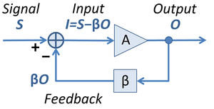
- Positive feedback system. Both op-amp Schmitt triggers are bipolar supplied op-amp circuits with positive feedback. In such a configuration (dual to the shown in the figure on the right), a portion of the output quantity (the op-amp output voltage here) is summed to the input quantity (the input voltage here). So, these circuits contain an attenuator (the β box in the figure) and a summer (the circle) in addition to the op-amp and, of course, the ubiquitous power supply.
Op-amp inverting Schmitt trigger 
Op-amp non-inverting Schmitt trigger


- Series configuration. In an op-amp inverting Schmitt trigger (see the figure on the left), attenuation and summation are separated. The two resistors act only as a "pure" attenuator (voltage divider) representing the β box in the figure. The input loop (Vin - Vdiff - VR1, according to KVL), acts as a series "summer" representing the "circle". These circuits are referred to as circuits with series feedback (an op-amp inverting Schmitt trigger and an op-amp non-inverting amplifier are typical positive and negative feedback examples).
- Parallel configuration. In an op-amp non-inverting Schmitt trigger (see the figure on the right), attenuation and summation are incorporated. The two resistors act both as an attenuator and as a summer. They form a weighted parallel summer representing the combination of the β box and the circle in the block diagram above. It is conditionally parallel since two perfect voltage sources (the input source and the op-amp output) are connected somehow "in parallel" (through resistors to the op-amp input as it is incorrect to connect directly perfect voltage sources in parallel). This configuration is an excellent illustration of the superposition principle where two partial voltages are superimposed at the node between the two resistors (see an impressive presentation). From this "system" viewpoint, a non-inverting Schmitt trigger and an inverting op-amp amplifier consist not of as many as three components (the resistors R1, R2 and an op-amp) but only of two components (a parallel summer R1,R2 and an op-amp). These circuits are referred to as circuits with parallel feedback (an op-amp non-inverting Schmitt trigger and an op-amp inverting amplifier are typical positive and negative feedback examples).
- Single-supply version. But let's return to our circuit. In this case, we have to connect another low-resistive voltage divider to create an artificial middle point ( virtual ground). But we may reduce this 4-resistor circuit to a 3-resistor one if we combine the two dividers into one 3-input summer that sums V+, ground potential and Vout. The op-amp impacts the "bad" virtual ground by the third ("load") resistor thus creating a hysteresis. I had described this clever trick (a purposely worsened virtual ground) in the virtual ground page (see the old revision) but it was removed:
- ... In some single-supplied circuits with positive feedback (for example, an op-amp inverting comparator with hysteresis named also op-amp Schmitt trigger), the virtual ground is preliminarily worsened. In this arrangements, this point has significant internal resistance, in order to be easily influenced by the op-amp output. The same trick of a "soft" virtual ground is frequently used in the single supply op-amp circuits with negative feedback...
- Later on, I started a discussion about this clever trick on virtual ground talk page. You may visit and join the discussion to improve the virtual ground page as well. Circuit dreamer ( talk, contribs) 15:55, 17 April 2010 (UTC)
- Despite the explanation dated April 17, 2010 by Circuit dreamer above, simple circuit analysis continues to show that the circuits as shown in the main article on April 16, 2010 (which are identical to those shown above) are simple inverting amplifiers.
- Here is a link to the output of a circuit analysis: http://img42.imageshack.us/img42/4968/nonamerc.jpg . (Sorry for the imageshack link, but pursuant to Wiki policy, I am not permitted to upload until after a four-day waiting period, and there is no time for that.) The link shows the so-called "non-inverting Schmitt trigger circuit", for some nominal values of R1=R2=20 kOhms, and Vcc = +/- 10V. Input to the circuit is a 5 kHz sine wave with amplitude of +/-4 V. As expected with R1=R2, the circuit has a gain of -1, and shows exactly that with an output exactly equal to the negative of the input.
- If the circuits shown in the article work only because of "clever tricks" plus real-world departures of actual op-amp devices from their ideal model, then the article should be modified to reflect that. 63.207.173.11 ( talk) 18:03, 17 April 2010 (UTC)
- I'm not sure what you've used to perform your analysis, but it's self-evidently incorrect. 30 seconds of thought ought to convince you that the instant a non-zero voltage is presented to V+, the op-amp output will head toward saturation. The op-amp will only present a -ve output for a +ve input if the frequency is so high that the internal phase shift reaches 180°; however for an op-amp with dominant-pole compensation (such as the 741), the gain at this point will be well below (-)1. Oli Filth( talk| contribs) 19:05, 17 April 2010 (UTC)
- The simulation package that was used was TINA-TI which is a lite (and free) version of Texas Instruments' SPICE-Based Analog Simulation Program, available here: http://focus.ti.com/docs/toolsw/folders/print/tina-ti.html . Seems reputable to me, but if you have knowledge that it's unreliable, let us know. As for your proposed "30 seconds of thought", it's precisely that thought that leads to the derivation of equations for a standard inverting amplifier: since the presence of a non-zero voltage at V+ would drive the op-amp output to saturation, the feedback to V+ causes the Vout output to be driven in a direction exactly opposite to the direction of Vin, through the resistor-divider of R1 for Vin and R2 for Vout. 63.207.173.11 ( talk) 19:49, 17 April 2010 (UTC)
- I'm trying to see what the problem is with your reasoning... Well, let's start a discussion about the circuit operation. The two resistors R1 and R2 constitute a simple resistive summing circuit having two inputs (the left end of R1 and the right end of R2) and one output (the common point between them). Imagine the output voltage is constant (the op-amp is in positive or negative saturation) and the input voltage source drives this circuit from left producing a partial voltage V+' = Vin.R2/(R1 + R2) at the non-inverting input. The op-amp drives the circuit from right producing a partial voltage V+" = Vout.R1/(R1 + R2). The resulting overall voltage is V+ = V+' + V+" = Vin.R2/(R1 + R2) + Vout.R1/(R1 + R2). When this voltage crosses the zero "line" (then |Vout|/|Vin| = R2/R1), it changes its sign and the output voltage begins changing. As these variations are applied at the non-inverting input, they make the output continue changing in the same direction until the output saturates. Of course, then loop gain has to be AOL.R1/(R1 + R2) > 1.
- Now let's compare the two versions - with negative and with positive feedback. In an inverting amplifier, the op-amp changes its output voltage to zero the overall voltage V- at the inverting input and finally reaches the equilibrium. In a non-inverting Schmitt trigger, the op-amp is "misled":); it changes its output voltage in a "wrong" direction and finally reaches the positive or the negative rail. So, the circuit is not an inverting amplifier; it only resembles this negative feedback circuit. Figuratively speaking, a non-inverting Schmitt trigger is an inverting amplifier with swapped inputs.
- There are more "symmetric" names for the two Schmitt triggers - non-inverting op-amp comparator with hysteresis and inverting op-amp comparator with hysteresis (indeed, the word "inverting" sounds a little confusing applied to this positive feedback circuit). Circuit dreamer ( talk) 22:04, 17 April 2010 (UTC)
- The math above seems clearly incorrect if it is being applied to the diagram labeled "Op-amp non-inverting Schmitt trigger" (i.e., the right-hand diagram, which is the topic at hand). It seems incorrect since the equation given for V+ at the non-inverting input (i.e., "V+ = V+' + V+" = Vin.R2/(R1 + R2) + Vin.R1/(R1 + R2)") sums identically to V+ = Vin which is obviously not right. If it were right, then the circuit would not be a Schmitt trigger, since V+ = Vin implies a pure saturation amplifier without the hysteresis that characterizes a Schmitt trigger.
- Using the standard assumption that the current drawn by V+ is zero, then for the diagram on the right, the voltage at V+ is a simple resistor-divider of V+ = (Vin - Vout)*R2/(R1+R2) + Vout. Since V- is tied to ground, then V+ = V- = 0 = (Vin - Vout)*R2/(R1+R2) + Vout, which leads easily to the result that Vout/Vin = - R2/R1, which is a simple inverting amplifier.
- This result of a simple inverting amplifier is supported by the circuit analysis posted at http://img42.imageshack.us/img42/4968/nonamerc.jpg , as mentioned above. 63.207.173.11 ( talk) 22:27, 17 April 2010 (UTC)
- I have finally realized what the problem is. Of course, at the moment just before the transition Vout/Vin = - R2/R1 and there is a virtual ground at the non-inverting input. But this does not mean that the circuit is an inverting amplifier. Furthermore, at (till) this point, the circuit is not an amplifier at all as the op-amp is saturated (it is just a "battery"). A moment later, during the very transition, V+ and Vout begin changing in the same direction (i.e., there is a positive feedback). Let's make a final conclusion.
- I recommend to you to examine an attractive real time presentation of an inverting amplifier by means of voltage diagram. Next week, I will conduct this interesting experiment with my students in the laboratory to show the virtual ground phenomenon in negative feedback circuits. After that, I will swap the op-amp inputs to "mislead" the op-amp and to convert this negative feedback circuit into positive one (our non-inverting Schmitt trigger). Circuit dreamer ( talk) 23:45, 17 April 2010 (UTC)
- There are inconsistencies in the description above, and these inconsistencies make the description unpersuasive. First, there is a concession that at the moment of transition, Vout/Vin = - R2/R1, in other words, that Vout and Vin have opposite signs. But then, in the "final conclusion", it is asserted that the circuit acts as a non-inverting amplifier (and indeed the caption for the circuit is "non-inverting Schmitt trigger"), which would infer that Vout and Vin have the same signs.
- Moreover, the equation derived by me (and supported by circuit analysis) makes absolutely no assumptions about the state of the op-amp or its output. The above description, however, makes a singularly unusual assumption, for which no justification is provided: that the op-amp starts with its output in a saturated state.
- Beacause of these inconsistencies, because the equations derived by me are fully consistent with standard models for ideal op-amps, and because these equations are supported by the circuit analysis, I continue to insist that the circuits are nothing more than inverting amplifiers. 63.207.173.11 ( talk) 23:55, 17 April 2010 (UTC)
(outdent) There is a lot of confused maths being thrown about here! Put simply, we have:
- Vout = A.(V+ - V-) = A.V+ (until saturation).
- V+ = (Vout + Vin)/2 (always true).
Whichever way you look at it, as soon as Vin becomes non-zero, Vout will initially tend in the same direction. As the feedback is positive, this will only pull the circuit further away from the solution to these equations (Vout/Vin = A/(2 - A) ≈ -1). Therefore, this solution is not stable. In other words, the only stable states of this circuit are with the output saturated at one of the rails. Oli Filth( talk| contribs) 00:27, 18 April 2010 (UTC)
- "...Therefore, this solution is not stable": This is the single most helpful comment posted yet, and I thank you for it. I see it now. The algebra of V+ = V- = 0 (in this case) would lead to a solution which might be algebraically correct of Vout/Vin = -1. However, the solution is not a stable mode of the circuit. I see, therefore, how the circuit operates as a Schmitt trigger with hysteresis.
- It still confuses me that the TINA-TI circuit analysis package (available from Texas Instruments here: http://focus.ti.com/docs/toolsw/folders/print/tina-ti.html ) gives an incorrect result, and shows a simple inverting amplifier. Here again is the link to the output of circuit analysis: http://img42.imageshack.us/img42/4968/nonamerc.jpg . But that's a topic to raise with TI and not here.
- I am posting this out of chronological order, above the following comment which was posted first. Hopefully that will not be viewed as too high a breach of etiquette. And thanks for the outdent. 63.207.173.11 ( talk) 17:10, 19 April 2010 (UTC)
- Latches. IMO, it is high time to move this discussion to flip-flop or latch page since we are already talking about the great positive feedback "ability" - to make amplifiers memorize. The "trick" (connecting the output of a non-inverting amplifier to its input) is extremely simple but the impact of this idea on the society is huge (latches, registers, counters, RAMs, computers...). I have been building step-by-step transistor and op-amp versions together with my students in the laboratory (these two stories are created by my students in 2008; so, be lenient to their creations). I have an idea to insert a text and image in the beginning of flip-flop page where to show the basic idea behind these legendary circuits. But let's return to our circuit... Circuit dreamer ( talk, contribs, email) 14:54, 18 April 2010 (UTC)
- Op-amp as integrator. Dear curious visitor, sorry, but these circuits are not negative feedback circuits (inverting amplifiers); they are exactly positive feedback circuits (latches)... The problem is that you try to understand some qualitative thing (what are these circuits?) by quantitative means and thus you have walked straight into the trap of formal analysis:) The situation is very indicative as it shows the helplessness of formal approach to explain circuits. Thinking of an op-amp in terms of VOUT = A.V+ (i.e., there is a proportion between V+ and VOUT and they change simultaneously), we fall into a vicious circle traveling the feedback loop; thus, we can never understand circuit operation. I came across this problem in 1986 when I began teaching analog electronics to my students and I was trying to explain negative feedback phenomenon to them. Then I began realizing the paradoxical fact that although an op-amp is really a proportional and, as they consider, an almost "non-inertial" device, in order to understand how op-amp circuits work, we have to think of it as an integrating, inertial device. So, let's forget (temporarily) all the equations above and let's try to realize what happens by intuition! Circuit dreamer ( talk, contribs, email) 14:59, 18 April 2010 (UTC)
- Integrator inside. The problem is that, during the transition, the op-amp is not an amplifier; it is an integrator driven by maximum input voltage (see op-amp myths, Integrator inside section). After the transition begins, the op-amp changes its output voltage with the maximum rate (for example, the ubiquitous 741 has a slew rate of 0.5V/microsecond). So, during the transition, there is no proportionality (A) between the input and output voltage; the op-amp is not a proportional device and the simple analysis above fails to describe the circuit operation. But it is more than obvious that the output voltage "moves" in the same direction as the input voltage V+ and continuously increases this voltage through the voltage divider R1-R2. As a result, the output voltage reaches one of the supply rails. Let's make conclusions:
- Positive feedback. In these positive feedback circuits, the op-amp is not an amplifier at the stable end states (positive or negative saturation); it is just a "battery". During the transition, the op-amp is not an amplifier as well; it is an integrator. Actually, in these positive feedback circuits, the op-amp is never an amplifier.
- Negative feedback. Circuits with negative feedback have the same problem. But there the op-amp manages to reach the equilibrium. So, here the conclusions are:
- In negative feedback circuits, the op-amp is not an amplifier only during the transition (at sharp input change); it is an integrator as above. After reaching the equilibrium, the op-amp becomes an amplifier again.
- Virtual ground. A month ago, I described this phenomenon (the op-amp inertness) in the virtual ground page (see the ground problems old revision)
- "...In response to an input voltage or current step, the op-amp output voltage does not change instantaneously; the finite circuit bandwidth results in a ramp-like initial response as with an integrator. As a result, the virtual ground moves from zero until the op-amp responds. For example, in the circuit of an inverting amplifier, Rf/(Rf + Rin) part of the input voltage appears at the virtual ground point..."
- and added a reference to the Barrie Gilbert's story... but the whole section about virtual ground problems was removed... Circuit dreamer ( talk, contribs, email) 15:06, 18 April 2010 (UTC)
- Signs. Finally, let's say some words about the signs. Indeed, it is confusing, but in these circuits, there are all the possible sign combinations (+ +, + -, - -, - +). They do not define whether the amplifier is inverting or non-inverting. Look at the directions of the input and the output voltage "movements": if they are the same, the circuit is non-inverting; if they are opposite, the circuit is inverting. Note also the inverting Schmitt trigger is implemented obligatory by an op-amp with a differential input while the non-inverting Schmitt trigger may be implemented by a single-ended non-inverting amplifier. That is why, the latter is a "non-inverting amplifier with positive feedback". Circuit dreamer ( talk, contribs, email) 16:01, 18 April 2010 (UTC)
Intuitive versus formal tools
Of course, circuits can be and have to be analyzed by formal methods but first basic ideas behind them have to be shown. At this first stage, mathematical expressions will not help us to grasp circuit ideas; they can't explain circuits. Formal methods will not answer all WHAT and HOW questions needed (what a problem electronic components solve, why they are connected there, what they actually do in circuits, how they do what they do, etc.) as they are quantitative tools while circuit ideas are something qualitative. It is more than obvious that we have to explain qualitative things by qualitative tools and quantitative things by quantitative tools. It is a great mistake to explain qualitative things by quantitative tools; at this stage, quantitative tools can serve only as secondary means.
Do not forget that these circuits have seen the light of day thanks to human fantasy, imagination and enthusiasm. We, human beings, understand, explain and even invent circuits by using our human intuition, imagination and emotions and only then we analyze, calculate and design them by using our reason, mind and intelligence. Circuits are systems of subsystems (functional blocks or more-elementary circuits consisting of components connected according to some clever idea). In order to understand/explain complex circuits, we have to discern/show these functional blocks (the basic op-amp circuits described in this page). For this purpose, we have to have very good notion about them.
Every, even the most elementary circuit solution, is based on some fundamental idea. When we see a new circuit and we try to understand it, we need to know this idea, the clever trick on which the circuit is based. Our page visitors need too the fundamental circuit ideas and concepts to understand circuits.
How to show circuit concepts in this page
In this current state, the article does not show the concepts behind op-amp applications. That is why, I would like to insert some text (two-three sentences) in the beginning of every op-amp application (subsection) where to show the basic idea. Some groups of circuits are based on the same general idea that may be shown in the beginning of the group. The problem is that now the op-amp circuits are classified only according to linearity. With the same success they may be classified by the presence of the feedback (without or with), by the kind of the feedback (negative or positive), by the way of feedback applying (parallel or series), etc. But the page will become too branched. So, I suggest to show (where it is possible) the general idea in the beginning of the common sections and to show the specific implementation in the beginning of the concrete subsections.
Circuit dreamer ( talk) 14:35, 2 April 2010 (UTC)
- I see this as a summary article. We don't need to explain the concepts of e.g. negative feedback for each and every circuit here; that should be explained more fully in its own article. The Operational amplifier article has a description of the principle; if that is not adequate then it is that article that should be improved!
- However, I do agree with you that the split between "linear" and "non-linear" is somewhat arbitrary (and questionable; the Wien oscillator relies on non-linear effects for instance, as does the Schmitt trigger). Therefore, I've removed these sub-headings. Oli Filth( talk| contribs) 14:48, 2 April 2010 (UTC)
I have restored the link to voltage compensation as the module is closely related to the topic. It considers op-amp inverting circuits with negative feedback (op-amp circuits with parallel negative feedback). Six of all the 18 op-amp circuits (1/3) are that sort of circuits: inverting amplifier, summing amplifier, integrator, differentiator, log converter and antilog converter.
In the beginning, the basic idea behind this kind of circuits is shown by step-by-step building scenario. Then, total of 8 op-amp circuits are considered thoroughly in the wikibooks module: inverting amplifier, capacitive integrator, capacitive differentiator, inductive integrator, inductive differentiator, log converter, antilog converter. The circuits are accompanied by informative time diagrams. Circuit dreamer ( talk, contribs, email) 12:31, 28 April 2010 (UTC)
- One of the reasons this material has been rejected from Wikipedia in the past is because it's painfully overworked and overcomplicated. I don't believe we should provide the reader with a link to similar material elsewhere, because it doesn't do them any favours. Oli Filth( talk| contribs) 14:32, 28 April 2010 (UTC)
- This story looks overworked as it reveals the philosophy behind these popular circuits by 9-step building procedure. It does not give a lot of ready-made circuits to readers; instead, it reveals the general idea behind them. This approach make readers think, not memorize... but it needs more words, time and efforts; that is why the story seems overcomplicated. The main use of "thinking instead memorizing" is that readers can understand and even create new circuits based on this powerful idea. The story will be interesting not only for beginners but for professionals as well (imagine what a pleasure is to find out the truth about these "never explained" circuits 20-30 years after graduation:) Circuit dreamer ( talk, contribs, email) 15:41, 28 April 2010 (UTC)
- "Overworked" is generally a bad thing! I don't believe this material increases the reader's understanding, it's just excessive verbosity, for what's really quite a simple concept. Therefore I don't believe that we should link to it, because it's unhelpful. I'm clearly not the only one who thinks this, because this type of material and analysis has been removed by many editors when you've tried to include in directly in Wikipedia.
- I'm going to remove the link again. If an indepdendent editor feels that it should be restored, then I'll accept that. But you shouldn't be repeatedly restoring links to your own material, because that sounds a bit close to a conflict of interest. Oli Filth( talk| contribs) 16:15, 28 April 2010 (UTC)
- I concur. This comes under the heading of Wikipedia:What_Wikipedia_is_not, ie: a textbook or technical manual. There are already too many external links that fall under this category. C-F's wikibooks should be the first to go IMHO. Zen-in ( talk) 17:55, 28 April 2010 (UTC)
I have placed a link to the applications section of Miller theorem as ten circuits with modified impedance belonging to op-amp applications article are closely related to Miller theorem. Here is the list of these circuits.
- Circuits with virtually increased up to infinite impedance
- Circuits with impedance converted to negative by current inversion
- Circuits with virtually zeroed impedance
Circuit dreamer ( talk, contribs, email) 17:50, 5 August 2010 (UTC)
Although I have taken the trouble to list the 10 op-amp circuits from this page closely related to Miller theorem, the link on the main article was deleted without any explanations why. I have restored the link because the fact that 10 of the total 17 circuits (60%) are related to Miller theorem is a good reason to place a link to it. Circuit dreamer ( talk, contribs, email) 18:27, 6 August 2010 (UTC)
- One link here is fine, but the corresponding section in Miller theorem ... was it really necessary? How is MT relevant for the basic voltage follower? It just works, with or without it... IMO the very fact that the article on MT needs the voltage follower - completely destroys the article's credibility. P.S. Cathode followers can be perfect. Ask Allen Wright about it. Perhaps examples from the RF world will be more relevant? East of Borschov 18:41, 6 August 2010 (UTC)
- Thank you for the comment as it is the first adequate reaction to Miller theorem. You are right; I have to say some words about it. Saying "theorem" I actually mean not the formal and abstract expressions; I mean something more "material" and natural - a set of clever tricks and techniques for artificially modifying circuit attributes (mainly impedance) by connecting an additional voltage source in series to the main input source. These techniques and circuit phenomena are separately well known from circuit design (e.g., bootstrapping, virtual ground, negative impedance, etc.) but the connection between them is not shown in sources. Miller theorem can show this connection (relationship); it can generalize them. Indeed, the classical presentations of Miller theorem only define the exact relation between the circuit attributes and show how to transform circuits to their equivalents; they do not mention its modifying abilities. In this page, I have emphasized just the modifying properties of this idea. In applications section, I have hierarchically organized various typical manifestations of this idea in six groups ("golden rules":); bootstrapping is one of them. Let's talk about it as you have already started this discussion.
- Bootstrapping means to neutralize the input voltage source by connecting in series an equal opposing voltage source. As a result, the input current is zero and the impedance seen from the side of the input source is infinite. In some cases (e.g., biasing circuits), this trick is introduced intentionally - an external impedance is connected between the two sources (the Miller's arrangement). In other cases (e.g., circuits with series negative feedback such as voltage follower), it is existing and inherent. In all these circuits, the input differential impedance of the differential amplifier connects (as a bridge) the input voltage source and the output voltage source (the amp's output) and we can't change these circumstances no matter if we want them. Fortunately, it is welcome effect because the output voltage neutralizes the input one; the current is zero and the impedance seen from the side of the input source is infinite (for an ideal amplifier).
- So, the role of the Miller theorem is to make a connection between these particular circuits and other apparently different circuits, to generalize this effect and, of course, to help calculating the input impedance (this is my answer to your question, "Was it really necessary?"). Miller theorem article "needs" the voltage follower as an example but, in acknowledgement of this service:), it "helps" the follower by explaining why the input impedance is so high. Note this is not a particular, specific only for this circuit explanation; it is a general explanation; it is a "golden rule": "To increase enormously the impedance, connect in series to the input voltage source (to the impedance) an equal opposing voltage source".
- As concerns the perfect (high input impedance) cathode, source and op-amp followers... this phenomenon make them more perfect up to ideal:) If you have more examples illustrating Miller's idea, please add them to the applications. Circuit dreamer ( talk, contribs, email) 23:52, 6 August 2010 (UTC)
- This is just more POV and OR like we have seen before. It is good that you are no longer assigning the benefits of negative resistance to virtually every electronic circuit but it appears you have just embarked on some other taxonomy. I thought we had disabused you of all this. Zen-in ( talk) 06:13, 7 August 2010 (UTC)
- I have added to Miller theorem applications maybe the most relevant (to this virtual infinite impedance phenomenon) example of voltage follower - the old fashioned potentiometric null-balance meter. From a nowadays viewpoint, this arrangement can be thought as a manually controlled voltage follower with series negative feedback. The supplying voltage source and the potentiometer constitute a regulated reference voltage source producing output voltage that is placed contrary and in series with the input voltage. Thus the two voltages are subtracted according to KVL and their difference is applied to the galvanometer acting as a zero indicator. The man monitors continuously the difference looking at the galvanometer and adjusts the output voltage equal to the input one. As a result, the resistance seen from the side of the input voltage source is virtually increased from a few hundred ohms (the actual galvanometer's resistance) up to the infinite resistance of an ideal voltmeter. Thus, thanks to Miller's virtual infinite impedance idea, the low-resistive ammeter (galvanometer) is converted to an ideal voltmeter (in respect to the internal resistance). Circuit dreamer ( talk, contribs, email) 12:15, 7 August 2010 (UTC)
I just cleaned up (I think) some commentary at the section on the "Inverting differentiator", but I'm not sure why it's there. The commentary isn't about issues implementing differentiators with operational amplifiers. Instead, it's about using differentiators in larger feedback loops. This may be a topic of interest, but it probably doesn't belong on this page and probably deserves a richer discussion. So should it be removed? Shouldn't this page just give the outline of the implementation of an OA-based inverting differentiator? — TedPavlic ( talk/ contrib/ @) 15:57, 12 July 2011 (UTC)
Zero crossing threshold detector duplicates a section here and should be merged for context. -- Wtshymanski ( talk) 22:03, 28 November 2011 (UTC)
- I reverted the redirect from Zero crossing threshold detector to this article, because too much information was omitted in the merge, including the references section and applications section. See WP:PRESERVE for more information. Northamerica1000 (talk) 14:24, 10 January 2012 (UTC)
Section "Inverting Integrator" has acquired most of article Op amp integrator
I have edited section "Inverting Integrator" to incorporate much of article Op amp integrator, per the suggestion in the banner at the beginning of this section. I have not attempted to merge in that article's section "Frequency response" nor "Applications" nor its reference. This work is a first cut and needs to include the derivation of the transfer function for each of the two circuits and it needs to include substantiation for the statement about the value of Rn.
I read the discussion above, titled "About the op-amp inverting integrator" and gave thought to how the concerns voiced there bore on the section. I hope I have addressed them reasonably well. ArthurOgawa ( talk) 09:01, 24 February 2014 (UTC)
Since Wikipedia is suppose to be helpful for "newbies", an important topic seems to be missing from this article and its parent operational amplifier article, which is how to properly terminate unused op-amps. I'm not sure which article it belongs, but I think a section should be created to address this important design issue, including the need for a drawing similar to "this drawing" which came from "this article". Please discuss and someone please add to the correct article. Thanks! • Sbmeirow • Talk • 16:09, 24 July 2014 (UTC)
- I deleted it from op amp. WP is not supposed to be a tutorial or a how to guide, so the material doesn't really belong in WP. This article appears to be a how to, so I left the EL in. Glrx ( talk) 23:37, 25 July 2014 (UTC)
- Proper design is NOT a "how to" guide. Maybe we should delete all the schematic drawings and calculations in all opamp articles, since they obviously show/tell a person "how to" make an opamp do "Negative feedback", "Inverting Amplifier", "Closed loop", and so on. I'm amazingly amazed at the deletion of this useful information. • Sbmeirow • Talk • 08:41, 26 July 2014 (UTC)
I wonder if someone could add the current-to-voltage converter configuration to this page? I was surprised to come here and not find it.
It's described here: /info/en/?search=Transimpedance_amplifier
For what it's worth, it's the fourth one on the corresponding french wikipedia page: http://fr.wikipedia.org/wiki/Montages_de_base_de_l%27amplificateur_op%C3%A9rationnel "Convertisseur courant à tension" = "Converter of current to voltage". Gwideman ( talk) 19:03, 29 April 2015 (UTC)
1. Under the logarithmic and the exponential sections, why are input and output voltage written as vin and vout instead of Vin and Vout? Are they small signal? I don't think they are.
2. Also, I've been trying to verify . If I use R=1 kΩ, Is=14.11e-9 A, Vin=1 V, I get -3.321e12 V. How is that possible? There must be something wrong. I think the extinction coefficient (n) should also be added for accuracy, including in the equation for the logarithmic output (VT should really be nVT).

ICE77 ( talk) 08:56, 4 August 2015 (UTC)
- For 1, I agree that those values seem to be large signal and should be and . I would encourage you make those changes!


- For 2, recall that it is exponential and so diverges very quickly—that makes a pretty huge input. Remember that a real opamp will saturate as it gets to the rails; if you have a modern rail-to-rail opamp, say with to power supply, your output will go all the way to maybe or so with good linearity, start plateauing, and then stop increasing at (this is just an example, check the datasheet for info relevant to an opamp you are using). You will most likely want to operate the circuit, with the parameters you mentioned, up to about () depending on your supply rails and linearity; note also that increasing your input simply to increases the theoretical output to .


- Many simplified models (e.g. in my second-year electronics course and many materials I learnt from at that time) do not mention the extinction coefficient. I think it would also be good to add, but in my opinion, it should be briefly explained with typical values, in order to ensure the article remains accessible to those without a strong devices background. Laogeodritt [ Talk | Contribs ] 05:19, 10 August 2015 (UTC)
Laogeodritt, thanks for the feedback.
1. I made the changes and they are live now.
2. After looking at the exponential increase of even small input voltages I have to agree that an output of 1V is unrealistic so that's why I got a huge output voltage. Clearly, the output would be clipped to near the lower supply rail. My simulation actually produces -13.77V at the output with an input of 1V and rails of ±15V. The extinction coefficient I have in my simulation is 1.984. It clearly needs to be included in the equation and it simply modifies the classic Schockley equation. If you don't include it, it's not practical. I would include it in the equations. After stepping the voltage from 0V to 1V in 100mV increments I noticed that the equation matches the simulation up to 300mV but then the equation diverges way too far when compared to the simulated values. I wonder what is the reason behind that. I also wonder what is a practical input voltage for the circuit in an actual application.
ICE77 ( talk) 05:21, 14 August 2015 (UTC)
Most of Japanese engineers still believe the term for "virtual short" should be "imaginary short" instead, because of a ridiculous textbook written in 1973, the famous author of which primarily told "imaginal short" which was later corrected to "imaginary short" for the grammatical sense. Nowadays, most Japanese engineers still believe it should be "imaginary" instead of "virtual" because their teachers never corrected the term who treated the textbook as "bible". It may seem nonsense, but translated Japanese terms apparently share the same meaning and thus they cannot understand the difference. So, er, is it okay to add "imaginary" in explanation with some historical description above? -- Wordmasterexpress ( talk) 06:13, 9 October 2015 (UTC)
- My opinion (being a relatively inactive Wikipedian nowadays):
- There is already an article on virtual grounds. Given that this is an encyclopaedia, not an EE learning resource, I believe that discussion on alternative terms would **not** be appropriate on this page, but **would** be appropriate at virtual ground. This article specifically mentions the concept in the "Practical considerations" section, which is a fairly introductory section, so you could edit that to read "virtual ground (or, occasionally, imaginary ground)" or something like that for clarity, but not include explanations to the term nor mention this synonym at other locations in the text---nonetheless, I think this is not ideal because they are not used universally synonymously (a certain number of Japanese engineers only is limited in scope) and the article's focus is not on this concept. The expectation is that you can click through to the virtual ground article to learn about that concept.
- As mentioned, I think this would be great to include as a discussion on the virtual ground page, to the effect of "In Japan, the term **imaginary ground** has found widespread/occasional use due to a 1973 textbook by Author [citation], which mistakenly used this term in the place of **virtual ground** [cite this claim]." Citing the textbook, and the statement that it's a mistake in terminology, would be important IMO, and avoid using emotional judgements like "ridiculous textbook" and "teachers ... treated the textbook as 'bible'" as it is unencyclopaedic, although if you can find citations for the details of the history and write it neutrally that would also be fine and in fact an interesting addition to that page! Laogeodritt [ Talk | Contribs ] 16:47, 10 October 2015 (UTC)
- Thank you for comments, Laogeodritt, and I apologize for not to respond for a long time. I will move the topic to virtual ground page, if nobody has done so. -- Wordmasterexpress ( talk) 10:32, 8 April 2016 (UTC)
- No problem! Talk pages are an inherently slow discussion, except for very activity-heavy articles. I'm just finding your response now. Laogeodritt [ Talk | Contribs ] 03:43, 15 July 2016 (UTC)
I have moved most html comments ( WP:HIDDEN) from the article to here for consideration. It is not satisfactory for the article to retain these long-term, and the material looks to be too "tutorial" in nature for an encyclopedic article.
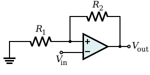
An inverting amplifier inverts and scales the input signal. As long as the op-amp gain is very large, the amplifier gain is determined by two stable external resistors (the feedback resistor Rf and the input resistor Rin) and not by op-amp parameters which are highly temperature dependent. In particular, the Rin–Rf resistor network acts as an electronic seesaw (i.e., a class-1 lever) where the inverting (i.e., −) input of the operational amplifier is like a fulcrum about which the seesaw pivots. That is, because the operational amplifier is in a negative-feedback configuration, its internal high gain effectively fixes the inverting (i.e., −) input at the same 0 V (ground) voltage of the non-inverting (i.e., +) input, which is similar to the stiff mechanical support provided by the fulcrum of the seesaw. Continuing the analogy,
- Just as the movement of one end of the seesaw is opposite the movement of the other end of the seesaw, positive movement away from 0 V at the input of the Rin–Rf network is matched by negative movement away from 0 V at the output of the network; thus, the amplifier is said to be inverting.
- In the seesaw analogy, the mechanical moment or torque from the force on one side of the fulcrum is balanced exactly by the force on the other side of the fulcrum; consequently, asymmetric lengths in the seesaw allow for small forces on one side of the seesaw to generate large forces on the other side of the seesaw. In the inverting amplifier, electrical current, like torque, is conserved across the Rin–Rf network and relative differences between the Rin and Rf resistors allow small voltages on one side of the network to generate large voltages (with opposite sign) on the other side of the network. Thus, the device amplifies (and inverts) the input voltage. However, in this analogy, it is the reciprocals of the resistances (i.e., the conductances or admittances) that play the role of lengths in the seesaw.
Hence, the amplifier output is related to the input as in
- .

So the voltage gain of the amplifier is where the negative sign is a convention indicating that the output is negated. For example, if Rf is 10 kΩ and Rin is 1 kΩ, then the gain is −10 kΩ/1 kΩ, or −10 (or −10 V/V). [1] Moreover, the input impedance of the device is because the operational amplifier's inverting (i.e., −) input is a virtual ground.


In a real operational amplifier, the current into its two inputs is small but non-zero (e.g., due to input bias currents). The current into the inverting (i.e., −) input of the operational amplifier is drawn across the Rin and Rf resistors in parallel, which appears like a small parasitic voltage difference between the inverting (i.e., −) and non-inverting (i.e., +) inputs of the operational amplifier. To mitigate this practical problem, a third resistor of value can be added between the non-inverting (i.e., +) input and the true ground. [2] This resistor does not affect the idealized operation of the device because no current enters the ideal non-inverting input. However, in the practical case, if input currents are roughly equivalent, the voltage added at the inverting input will match the voltage at the non-inverting input, and so this common-mode signal will be ignored by the operational amplifier (which operates on differences between its inputs).

Amplifies a voltage (multiplies by a constant greater than 1)

- Input impedance
- The input impedance is at least the impedance between non-inverting () and inverting () inputs, which is typically 1 MΩ to 10 TΩ, plus the impedance of the path from the inverting () input to ground (i.e., in parallel with ).
- Because negative feedback ensures that the non-inverting and inverting inputs match, the input impedance is actually much higher. dubious – discuss
- Although this circuit has a large input impedance, it suffers from error of input bias current.
- The non-inverting () and inverting () inputs draw small leakage currents into the operational amplifier.
- These input currents generate voltages that act like unmodeled input offsets. These unmodeled effects can lead to noise on the output (e.g., offsets or drift).
- Assuming that the two leaking currents are matched, their effect can be mitigated by ensuring the DC impedance looking out of each input is the same.
- The voltage produced by each bias current is equal to the product of the bias current with the equivalent DC impedance looking out of each input. Making those impedances equal makes the offset voltage at each input equal, and so the non-zero bias currents will have no impact on the difference between the two inputs.
- A resistor of value
- which is the equivalent resistance of in parallel with , between the source and the non-inverting () input will ensure the impedances looking out of each input will be matched.
- The matched bias currents will then generate matched offset voltages, and their effect will be hidden to the operational amplifier (which acts on the difference between its inputs) so long as the CMRR is good.
- Very often, the input currents are not matched.
- Most operational amplifiers provide some method of balancing the two input currents (e.g., by way of an external potentiometer).
- Alternatively, an external offset can be added to the operational amplifier input to nullify the effect.
- Another solution is to insert a variable resistor between the source and the non-inverting () input. The resistance can be tuned until the offset voltages at each input are matched.
- Operational amplifiers with MOSFET-based input stages have input currents that are so small that they often can be neglected.


References
- ^ Basic Electronics Theory, Delton T. Horn, 4th ed. McGraw-Hill Professional, 1994, p. 342–343.
- ^ Malmstadt, Enke and Crouch, Electronics and Instrumentation for Scientists, The Benjamin/Cummings Publishing Company, Inc., 1981, ISBN 0-8053-6917-1, Chapter 5. p. 118.
I left the following two comments (shown in green here) for later investigation:
- The relationship between input signal and output signal is now:
correction to come—ArthurOgawa

-
Single supply op-amp circuit collection
should link directly to TI
|
| This article is rated B-class on Wikipedia's
content assessment scale. It is of interest to the following WikiProjects: | ||||||||||
| |||||||||||
Stuff copied here from op-amp page in preparation.
Op-amps have applications as artificial neurons in neural nets. Specifically, as a number of summer amplifiers attached to a central amplifier attached to a comparator or schmitt trigger. For details, see http://www.rgu.ac.uk/files/chapter10%20-%20implementing%20ANNs.pdf
The correct term for this cct is Ideal Diode. The term super suggests something thats actually better than a diode. This term super diode is not used in electronics (not that Ive heard of) and should therfore be changed to ideal diode.-- Light current 17:44, 29 September 2005 (UTC)
- It is actually better than a diode. :-)
- I've seen the terms "super diode" and "precision diode" and simply "precision half-wave rectifier". The latter is the most accurate. I haven't seen it called an "ideal diode". (Oh wait. Here is one example.)
- [1] [2]
- This should be at Talk:Super diode, anyway. — Omegatron 19:26, 29 September 2005 (UTC)
- the ideal diode, as the name says, is something ideal that does not actually exist: it has a threshold of 0V and can bare tensions up to without letting any current pass through. The super diode has a behaviour that is very similar to the ideal one, but it's threshold is about (that is small, but not zero), and the range of voltages it can bare is not unlimited. Alessio Damato 15:22, 7 October 2005 (UTC)
- Exactly. I think "precision rectifier" is a "less slangy" term. — Omegatron 18:24, 7 October 2005 (UTC)
CAn we change it then to precision rectifier?-- Light current 19:36, 7 October 2005 (UTC)
Yes it is better than a diode. Its ideal but not super-- which would imply-- well Im not sure what it implies. I should have said better somehow than an Ideal diode. The term super as applied to electronics/electrical engineering (apart from superconductor) is outside my professional experience - Light current 22:11, 29 September 2005 (UTC)
THis statement seems to convey very little useful info. I think its wrong anyway. I will delete unless it can be tightened up-- Light current 01:15, 30 September 2005 (UTC)
Expunged useless stuff-- Light current 18:05, 12 October 2005 (UTC)
Addition: Whereas Input-Bias Current is more or less independent from the input voltage difference, it depends on temperature. Neither is output current dependent on the output voltage, as long as the opamp is capable do deliver that current. Therefor, in- and output-impedance are missleading terms in this context; impedance is used to discribe current variation caused by voltage change. This ratio is neither constant for in- nor outputs of opamps. — Preceding unsigned comment added by 83.65.147.83 ( talk) 20:36, 20 November 2012 (UTC)
Generally, we want to cover opamp circuits the way they are used, not as variations of a universal configuration, so I'm not sure these recent edits are that helpful. Maybe you could put something like that in the differential amplifier article, showing the connection between diff amps and all the other varieties? (I did the same thing with a "universal transistor amplifier", and it's not a great idea. See Talk:Common collector, for example.)
Although the use of HTML to represent math in articles is somewhat contentious, using complicated HTML to simulate the same effect as TeX is definitely bad, and mixing both within the same equation is very bad. Can you restore them to TeX? — Omegatron 04:16, 2 November 2005 (UTC)
- I edited the op amp page because the edit would have helped me in my ECE class if it were there when I first looked it up. You said that "Generally, we want to cover opamp circuits the way they are used" - however obviously we can't go through every permutation of an op amp circuit - we need general cases to consolidate knowlege into learnable peices. I rearranged the page because it showed very clearly that some circuits were special cases of the differential circuit. So not only does it show the special cases now, but it shows where the special cases come from more clearly than before. My goal for this page is to display a even more general op amp circuit so that you can use one equation for any op amp circuit consisting of resistors and power supplys. Fresheneesz 23:14, 8 November 2005 (UTC)
- So I guess it depends on what our goal for this article is. Is it a teaching tool or a reference?
- I doubt it's a great teaching tool, anyway. The problem with using a "universal amplifier" to teach all the various permutations is that the student won't recognize the permutations when they see them later. I was taught transistor amplifiers by saying that all the various types were variants on a universal transistor amplifier and I didn't learn them that well. I tried to add this to the various articles like common collector and it was (rightly) removed. I'm not sure this is a great idea.
- We should probably just show both renditions of the same circuits, or maybe move the universal diff amp stuff to the differential amp article, and leave this one as a reference. —
Omegatron 15:42, 9 November 2005 (UTC)
- Well, I see what you're saying. And I do take wikipedia to be a reference not a "learning tool" - despite the fact that you can learn a huge amount from reading reference material. The thing is, here, the article still keeps all the diagrams of - and explanation for - the circuits that were previously displayed as stand alone circuits. However it adds the element of some being permutations of others. So students using wikipedia to learn about op amps will see not only the specific differences between non-inverting, inverting, and differencing amplification circuits, but can also generalize the equations and be able to more easily remember how an op amp works. In my experience, I've found that one hard-to-learn equation beats out learning many small equations - you'll always be doing more work learning the many small equations. I think adding the permutations to the differencing amplifier page would be much more obscure - I know I wouldn't look for equations about an inverting amplifier in the differencing amplifer page.
Fresheneesz 02:47, 10 November 2005 (UTC)
- But all of these circuits are permutations of each other. It's just a matter of perspective. You say that the inverting amp is a simplification of the differential amp; I say that the differential amp is a combination of a voltage divider and an inverting amp. Which of us is right?
- I'm going to remove those bits and leave it the way it was before; categorized by topology only. (So the only simplifications of the differential amp are the ones that have certain resistor values, but still the same layout.) — Omegatron 16:11, 21 February 2006 (UTC)
- Well, I see what you're saying. And I do take wikipedia to be a reference not a "learning tool" - despite the fact that you can learn a huge amount from reading reference material. The thing is, here, the article still keeps all the diagrams of - and explanation for - the circuits that were previously displayed as stand alone circuits. However it adds the element of some being permutations of others. So students using wikipedia to learn about op amps will see not only the specific differences between non-inverting, inverting, and differencing amplification circuits, but can also generalize the equations and be able to more easily remember how an op amp works. In my experience, I've found that one hard-to-learn equation beats out learning many small equations - you'll always be doing more work learning the many small equations. I think adding the permutations to the differencing amplifier page would be much more obscure - I know I wouldn't look for equations about an inverting amplifier in the differencing amplifer page.
Fresheneesz 02:47, 10 November 2005 (UTC)
In some other encyclopedias this material is splitted into several articles. To generate cross-language links, the header references are used (for instance, . Please avoid changing the headers without the real need. Audriusa 20:38, 2 January 2006 (UTC)
en:Operational amplifier applications#Differentiator
- Alternatively, feel free to change the section titles, just put an {{ anchor}} to the old name in the same place. — TedPavlic ( talk/ contrib/ @) 14:17, 6 January 2010 (UTC)
We should include Breakpoint generators here.-- HappyEater 16:40, 19 May 2007 (UTC)
In the explanation for the non-inverting amp, the resistor subscripts don't correspond to the picture. "A third resistor, of value R_\mathrm{f} \| R_\mathrm{in}, added between the Vin source and the non-inverting input, while not necessary, minimizes errors due to input bias currents."
I looked everywhere for what the contributor meant by "R1||R2" and couldn't find any references besides: 'parallel-to' in geometry; and a logical OR operator in C programming. I don't think it means either of those and might possibly be a typo for "R1/R2". This needs to be verified by someone with more knowledge than myself.
- The symbol means "impedance of the parallel combination of". That is, . I've updated the document in the case you're talking about (for the inverting amplifier). I've also clarified the issues involving bias currents and input impedance. Some of the new comments there apply equally as well to any of the other OA circuits. — TedPavlic | ( talk) 21:03, 19 November 2008 (UTC)
I have often noticed a tendency to confusion around this term. I believe the usage is to call this circuit with an opamp and two matched pairs of resistors, a "Difference Amplifier". "Differential Amplifier" is the term used to name the input stage inside the opamp, as you will see if you follow the link to that article. Friendly Person ( talk) 13:31, 19 June 2008 (UTC)
If a fig is not provided for the "Zero level detector" "section", the section should be removed. — TedPavlic ( talk) 14:35, 26 January 2009 (UTC)
The diagram for this is incorrect. One of the input buffer amplifiers has the '+' and '-' inputs transposed. 20.133.0.13 ( talk) 13:37, 17 February 2009 (UTC)
Sorry, I have removed the link to the page about Philbrick absolutely involuntarily. I have no idea how it has happened and I was unpleasantly surprised when I saw Zen-in's remark. Philbrick is a legend; I highly appreciate his achievements. Circuit-fantasist ( talk) 15:35, 20 March 2009 (UTC)
There is currently a page dedicated to the inverting amplifier configuration of the op amp. The page doesn't seem to add much value beyond what is already in Operational amplifier applications or Operational amplifier. Merge? Scottr9 ( talk) 14:41, 23 April 2009 (UTC)
- I'd say so. Noodle snacks ( talk) 08:31, 27 April 2009 (UTC)
- Not all inverting amplifiers involve operational amplifiers, so there could be a case for a separate page for them, BUT the existing page is not it, as it stands (because it assumes opamps). I think there should be a bit of mention of inverting and non-inverting amplifiers in general terms in the amplifier article, as well as some discussion somewhere of the relevance of inverting amplifiers to absolute phase and the idea that an even number of inverting stages tending to have lower distortion. Maitchy ( talk) 05:33, 4 May 2009 (UTC)
There is an orphaned Log_amplifier page. The quality of that page is awful, but I would suggest actually keeping it and merging it with the Logarithmic Output from this page (and hopefully improving the content of the log amp page!).
Thus, Logarithmic output would have it's own main page and the section in this page could be excerpted from that article. This would be similar to how the Operational_amplifier_applications#Precision_rectifier section is handled with the Precision_rectifier main page.
Furthermore, something should be done to connect the Logarithmic_video_amplifier page.
Marangu ( talk) 13:21, 21 May 2009 (UTC)
The text on power supply design contained some very odd wording that I regard as meaningless. I have edited to remove the offending text, but if anyone can supply a meaningful alternative then please insert. —Preceding unsigned comment added by 86.53.81.124 ( talk) 16:52, 28 December 2009 (UTC)
- Restored from your edit and tried to add some clarity. You can find an example circuit that uses current on the OA rails as an input to an external amplifier in Horowitz and Hill. In particular, look at the notable examples (the gray section) at the end of the operational amplifier section. There is a high gain amplifier there (provided without explanation) that matches the text I've inserted. — TedPavlic ( talk/ contrib/ @) 06:02, 29 December 2009 (UTC)
The role of the op-amp in this circuit is to compensate the voltage drop across the capacitor. For this purpose, the op-amp adds so much voltage to the input voltage as it loses across the capacitor. The properly supplied op-amp acts as a compensating voltage source connected in series to the capacitor and the input voltage source.
This idea may be generalized for all the op-amp inverting circuits with parallel negative feedback (e.g., Inverting amplifier, Summing amplifier, Differentiator, Logarithmic output, Exponential output from this page). In all these circuits the op-amp compensates the voltage drop across the element connected between the output and the inverting input by adding the same voltage to the input voltage as it loses across this element. See also Voltage Compensation. Circuit dreamer ( talk) 18:38, 30 March 2010 (UTC)
- Two reasons why this has been removed:
- This is a non-standard explanation (whilst it's true, I've never seen it described like this).
- Even if it were true, it applies to all negative-feedback topologies, so it's unnecessary to add this detail to purely the integrator and differentiator.
- Oli Filth( talk| contribs) 10:46, 31 March 2010 (UTC)
- The page. Let's first see what happens if someone curious web reader wants to understand what an op-amp integrator is. Of course, he/she will write "op-amp integrator" in the Google window and will see this Wikipedia page at the first place from all these 100000 pages. The visitor trusts to Wikipedia, chooses Integrator from the contents and begins reading. Now answer me frankly: Will the visitor understand what this circuit does, what is the great basic idea behind it, how it operates, if there is some connection with the passive RC version, with what purpose an op-amp is added to the passive version, what the op-amp actually does in this active version, why the circuit is inverting...? Unfortunately, the visitor will not get answers to these questions from this page... For now, he/she will learn that "the integrator integrates the (inverted) signal over time", will learn the expression and will come to know that the circuit has a lot of problems... The situation with the rest of the sections is similar. In this state, the page looks like a chapter of a cookbook. But, if you please, Wikipedia is not a cookbook...
- The sections. It is obvious that every section of this page dedicated to one of these legendary op-amp applications, has to say some words about the purpose (what it does), the basic idea behind circuit (how it is implemented), the expression, the operation (how it does what it does), the imperfections (problems) and the applications. Of course, some of these parts may be omited, depending on the specific circuits but the basic idea has to be shown in the beginning.
- The voltage compensation idea. This idea is extremely simple and I vonder why "you've never seen it described like this". I met this powerful idea in the end of 70s (see the talk page) but I realized it only in the early 1990s. Thereafter I make my students realize and use it to build "ideal" devices (circuits): diodes, capacitors, etc. But it is not only an "electrical" idea; you may see the compensation idea everywhere around you in this world. During our life, we, human beings, continously compensate harmful quantities by useful ones; as a result we obtain zero result (virtual ground). You may see this phenomenon even here, in Wikipedia: when some vandal removes valuable text (a harmful action), we return the same text (an equivalent useful action) and the result is zero (a virtual ground).
- The integrator. Well, let's see this idea in the op-amp integrator (see also How to Make a Perfect RC-integrator, How do we build an op-amp RC integrator? and Building an op-amp inverting integrator). What is the problem of the simple passive RC integrator? The voltage across the capacitor is the problem as it is subtracted from the input voltage; it "enervates" the input voltage source. So, this voltage is harmful and we have to compensate it. For this purpose, we connect an additional voltage source (the output of a properly supplied op-amp) in series to the capacitor and make the op-amp adjust its output voltage so that it is always equal to the voltage across the capacitor. Actually, this voltage adds to the input voltage and thus compensates the voltage across the capacitor. Let's consider the signs traveling along the circuit of four elements and beginning from the ground. If the input voltage is positive and constant, the output voltage is negative; the two voltage sources are connected in series in the same direction (-Uin+, -Uout+). You may think of this combination as of a compound voltage source (Vin + Vout) that passes a constant current through the resistor that does not depend on the voltage across the capacitor...
- (to be continued) Circuit dreamer ( talk) 20:54, 31 March 2010 (UTC)
- The properties of all of the negative-feedback examples can be trivially derived by standard circuit analysis and the added constraint that V- = V+. At most, we should present the standard analysis, not this non-standard explanation that "the op-amp compensates for the voltage drop". Oli Filth( talk| contribs) 21:30, 31 March 2010 (UTC)
- No matter how much you try to sell your idiosynchratic view of electronics, it just doesn't belong in Wikipedia articles. Electronic circuits are very easily and clearly described with mathematical expressions derived from incremental analysis. Most people with an interest in electronics ( this includes Circuit dreamer ) don't bother with the analysis - they just use well-known mathematical expressions. The same is true about Physics. When you calculate the mileage (or km/litre) of your car , you use a well-known calculation. I don't believe that you, Circuit dreamer ascribe the phenomena of gas consumption in your car to another branch of idiosynchratic thought (such as enervated over-helpers resisting the consumption of petrol...), or that you expain this effect with smiling/frowning stickmen and multi-colored diagrams. So why do you persist in trying to explain electronics that way? You use the mathematical expressions which are based on valid and accepted physical approximations. Your attempts to describe electronics in this idiosynchratic manner is inconsistent. And unfortunately for you the results are often the syntactic equivalent of painting yourself into a corner. Despite English being my native language, I would find it equally difficult. While it might seem to make sense to you, after you have completed that very difficult task, the results can not be comprehended by anyone else. I thought we had disabused you of this habit a few months ago. Zen-in ( talk) 01:50, 1 April 2010 (UTC)
- Thank you for these so interesting thoughts. Really, you are right that in our routine we do not reason in depth; instead, we act mechanically. I don't know even how much is the gas consumption in my car (I prefer to think about circuit ideas while I drive it:) But if some time I want to know what the phenomena of gas consumption is, I will visit the according Wikipedia page and then I will need such kind of "smiling/frowning stickmen and multi-colored diagrams":) Also, this depends on the people - there are people that do not think about anything in this world (they will probably never visit Wikipedia) and v.v., there are curious people that think about everything in depth.
- Well, let's now move in electronics area. I know that most people (including circuit designers as well) use ready-made circuit solutions from op-amp applications handbooks. But they frequently do not find human-friendly explanations there as producers are not interested to reveal circuit ideas; instead, they are interested to advertise their wares. Then, the reader is most likely to visit this Wikipedia page in the hope of understanding the circuit idea and he/she will be thankful to get answers to all the questions above. Circuit dreamer ( talk) 15:42, 2 April 2010 (UTC)
Regarding to the sign of the feedback, there are two kinds of circuits with feedback - circuits with negative feedback (e.g., inverting and non-inverting amplifier) and circuits with positive feedback (e.g., non-inverting and inverting Schmitt trigger).
Regarding to the way of feedback applying, there are two kinds of circuits with feedback - circuits with parallel feedback (inverting amplifier and non-inverting Schmitt trigger) and circuits with series feedback (non-inverting amplifier and inverting Schmitt trigger).
In circuits with parallel feedback (look at the picture of the inverting amplifier above and at the picture of the non-inverting Schmitt trigger here), the op-amp's output and the input voltage source are connected through the feedback circuit (the resistors R1 and R2). As a result, the op-amp passes a current through the input source; so, the circuit impacts the input source. Note that in circuits with parallel negative feedback (inverting amplifier) the two voltage sources are connected in the same direction travelling through the circuit; so their voltages are added; in circuits with parallel positive feedback (non-inverting Schmitt trigger) the two voltage sources are connected in the opposite direction; so their voltages are subtracted. Now look at the circuit of NIC (more precisely, it is a VNIC) that is a typical S-shaped negative resistor, and you will see the same phenomenon there - the op-amp's output and the input voltage source are connected through the positive feedback circuit (the resistors R3 and the internal resistor of the input source Vs). That is why the non-inverting Schmitt trigger behaves as a (an S-shaped) negative resistor. See also Linear Mode of Current Inversion NIC and Bistable Mode of Current Inversion NIC.
In circuits with series feedback (look at the picture of the non-inverting amplifier above and at the picture of the inverting Schmitt trigger here), there is no connection between the op-amp's output and the input voltage source. So, no current flows between them and these circuits do not possess a negative resistance; they have extremely high input resistance. Circuit dreamer ( talk) 20:33, 30 March 2010 (UTC)
- This idea you have, that almost everything in electronics is due to a negative resistance was pretty much talked to death a while ago. It is OR and your own POV. No-one else subscribes to your theory, sorry. Also, I thought you had agreed to not post anymore of your "circuit ideas". Zen-in ( talk) 00:32, 31 March 2010 (UTC)
As of today (April 16, 2010), both of the Schmitt trigger versions seem clearly wrong. Both need a third resistor, to establish a resistor-divider between +5v and ground. As they stand now, without the third resistor, they are merely variations of the inverting and non-inverting amplifiers. —Preceding unsigned comment added by 63.207.173.11 ( talk) 20:35, 16 April 2010 (UTC)
- Well here are references that say they do work for the first circuit and for the second circuit. SpinningSpark 21:19, 16 April 2010 (UTC)
- Both of those links precisely show the third resistor that I refer to.
- Here's another link, which also shows the third resistor: http://hyperphysics.phy-astr.gsu.edu/hbase/electronic/schmitt.html —Preceding unsigned comment added by 63.207.173.11 ( talk) 22:38, 16 April 2010 (UTC)
- No they don't. The third resistor in both examples is merely a load resistor on the output of the op-amp and has nothing to do with the hysterisis action of the circuit. The circuit you have linked is different from both of those. SpinningSpark 23:20, 16 April 2010 (UTC)
Replace (-) with (+) in this negative feedback configuration to obtain a positive feedback version
- Both the Wikipedia circuits are right and they do not need a third resistor as they are bipolar-supply op-amp circuits. The third resistor in the single-supply inverting configuration is not only a load resistor on the output of the op-amp; instead, it is closely related to the hysteresis action of the circuit... and this is a clever circuit trick related to virtual ground applications... But let me show, in human friendly manner (by means of "tortuous" explanations:), what the problem is... the philosophy behind these legendary circuits... Circuit dreamer ( talk) 15:55, 17 April 2010 (UTC)
- Positive feedback system. Both op-amp Schmitt triggers are bipolar supplied op-amp circuits with positive feedback. In such a configuration (dual to the shown in the figure on the right), a portion of the output quantity (the op-amp output voltage here) is summed to the input quantity (the input voltage here). So, these circuits contain an attenuator (the β box in the figure) and a summer (the circle) in addition to the op-amp and, of course, the ubiquitous power supply.
Op-amp inverting Schmitt trigger Op-amp non-inverting Schmitt trigger
- Series configuration. In an op-amp inverting Schmitt trigger (see the figure on the left), attenuation and summation are separated. The two resistors act only as a "pure" attenuator (voltage divider) representing the β box in the figure. The input loop (Vin - Vdiff - VR1, according to KVL), acts as a series "summer" representing the "circle". These circuits are referred to as circuits with series feedback (an op-amp inverting Schmitt trigger and an op-amp non-inverting amplifier are typical positive and negative feedback examples).
- Parallel configuration. In an op-amp non-inverting Schmitt trigger (see the figure on the right), attenuation and summation are incorporated. The two resistors act both as an attenuator and as a summer. They form a weighted parallel summer representing the combination of the β box and the circle in the block diagram above. It is conditionally parallel since two perfect voltage sources (the input source and the op-amp output) are connected somehow "in parallel" (through resistors to the op-amp input as it is incorrect to connect directly perfect voltage sources in parallel). This configuration is an excellent illustration of the superposition principle where two partial voltages are superimposed at the node between the two resistors (see an impressive presentation). From this "system" viewpoint, a non-inverting Schmitt trigger and an inverting op-amp amplifier consist not of as many as three components (the resistors R1, R2 and an op-amp) but only of two components (a parallel summer R1,R2 and an op-amp). These circuits are referred to as circuits with parallel feedback (an op-amp non-inverting Schmitt trigger and an op-amp inverting amplifier are typical positive and negative feedback examples).
- Single-supply version. But let's return to our circuit. In this case, we have to connect another low-resistive voltage divider to create an artificial middle point ( virtual ground). But we may reduce this 4-resistor circuit to a 3-resistor one if we combine the two dividers into one 3-input summer that sums V+, ground potential and Vout. The op-amp impacts the "bad" virtual ground by the third ("load") resistor thus creating a hysteresis. I had described this clever trick (a purposely worsened virtual ground) in the virtual ground page (see the old revision) but it was removed:
- ... In some single-supplied circuits with positive feedback (for example, an op-amp inverting comparator with hysteresis named also op-amp Schmitt trigger), the virtual ground is preliminarily worsened. In this arrangements, this point has significant internal resistance, in order to be easily influenced by the op-amp output. The same trick of a "soft" virtual ground is frequently used in the single supply op-amp circuits with negative feedback...
- Later on, I started a discussion about this clever trick on virtual ground talk page. You may visit and join the discussion to improve the virtual ground page as well. Circuit dreamer ( talk, contribs) 15:55, 17 April 2010 (UTC)
- Despite the explanation dated April 17, 2010 by Circuit dreamer above, simple circuit analysis continues to show that the circuits as shown in the main article on April 16, 2010 (which are identical to those shown above) are simple inverting amplifiers.
- Here is a link to the output of a circuit analysis: http://img42.imageshack.us/img42/4968/nonamerc.jpg . (Sorry for the imageshack link, but pursuant to Wiki policy, I am not permitted to upload until after a four-day waiting period, and there is no time for that.) The link shows the so-called "non-inverting Schmitt trigger circuit", for some nominal values of R1=R2=20 kOhms, and Vcc = +/- 10V. Input to the circuit is a 5 kHz sine wave with amplitude of +/-4 V. As expected with R1=R2, the circuit has a gain of -1, and shows exactly that with an output exactly equal to the negative of the input.
- If the circuits shown in the article work only because of "clever tricks" plus real-world departures of actual op-amp devices from their ideal model, then the article should be modified to reflect that. 63.207.173.11 ( talk) 18:03, 17 April 2010 (UTC)
- I'm not sure what you've used to perform your analysis, but it's self-evidently incorrect. 30 seconds of thought ought to convince you that the instant a non-zero voltage is presented to V+, the op-amp output will head toward saturation. The op-amp will only present a -ve output for a +ve input if the frequency is so high that the internal phase shift reaches 180°; however for an op-amp with dominant-pole compensation (such as the 741), the gain at this point will be well below (-)1. Oli Filth( talk| contribs) 19:05, 17 April 2010 (UTC)
- The simulation package that was used was TINA-TI which is a lite (and free) version of Texas Instruments' SPICE-Based Analog Simulation Program, available here: http://focus.ti.com/docs/toolsw/folders/print/tina-ti.html . Seems reputable to me, but if you have knowledge that it's unreliable, let us know. As for your proposed "30 seconds of thought", it's precisely that thought that leads to the derivation of equations for a standard inverting amplifier: since the presence of a non-zero voltage at V+ would drive the op-amp output to saturation, the feedback to V+ causes the Vout output to be driven in a direction exactly opposite to the direction of Vin, through the resistor-divider of R1 for Vin and R2 for Vout. 63.207.173.11 ( talk) 19:49, 17 April 2010 (UTC)
- I'm trying to see what the problem is with your reasoning... Well, let's start a discussion about the circuit operation. The two resistors R1 and R2 constitute a simple resistive summing circuit having two inputs (the left end of R1 and the right end of R2) and one output (the common point between them). Imagine the output voltage is constant (the op-amp is in positive or negative saturation) and the input voltage source drives this circuit from left producing a partial voltage V+' = Vin.R2/(R1 + R2) at the non-inverting input. The op-amp drives the circuit from right producing a partial voltage V+" = Vout.R1/(R1 + R2). The resulting overall voltage is V+ = V+' + V+" = Vin.R2/(R1 + R2) + Vout.R1/(R1 + R2). When this voltage crosses the zero "line" (then |Vout|/|Vin| = R2/R1), it changes its sign and the output voltage begins changing. As these variations are applied at the non-inverting input, they make the output continue changing in the same direction until the output saturates. Of course, then loop gain has to be AOL.R1/(R1 + R2) > 1.
- Now let's compare the two versions - with negative and with positive feedback. In an inverting amplifier, the op-amp changes its output voltage to zero the overall voltage V- at the inverting input and finally reaches the equilibrium. In a non-inverting Schmitt trigger, the op-amp is "misled":); it changes its output voltage in a "wrong" direction and finally reaches the positive or the negative rail. So, the circuit is not an inverting amplifier; it only resembles this negative feedback circuit. Figuratively speaking, a non-inverting Schmitt trigger is an inverting amplifier with swapped inputs.
- There are more "symmetric" names for the two Schmitt triggers - non-inverting op-amp comparator with hysteresis and inverting op-amp comparator with hysteresis (indeed, the word "inverting" sounds a little confusing applied to this positive feedback circuit). Circuit dreamer ( talk) 22:04, 17 April 2010 (UTC)
- The math above seems clearly incorrect if it is being applied to the diagram labeled "Op-amp non-inverting Schmitt trigger" (i.e., the right-hand diagram, which is the topic at hand). It seems incorrect since the equation given for V+ at the non-inverting input (i.e., "V+ = V+' + V+" = Vin.R2/(R1 + R2) + Vin.R1/(R1 + R2)") sums identically to V+ = Vin which is obviously not right. If it were right, then the circuit would not be a Schmitt trigger, since V+ = Vin implies a pure saturation amplifier without the hysteresis that characterizes a Schmitt trigger.
- Using the standard assumption that the current drawn by V+ is zero, then for the diagram on the right, the voltage at V+ is a simple resistor-divider of V+ = (Vin - Vout)*R2/(R1+R2) + Vout. Since V- is tied to ground, then V+ = V- = 0 = (Vin - Vout)*R2/(R1+R2) + Vout, which leads easily to the result that Vout/Vin = - R2/R1, which is a simple inverting amplifier.
- This result of a simple inverting amplifier is supported by the circuit analysis posted at http://img42.imageshack.us/img42/4968/nonamerc.jpg , as mentioned above. 63.207.173.11 ( talk) 22:27, 17 April 2010 (UTC)
- I have finally realized what the problem is. Of course, at the moment just before the transition Vout/Vin = - R2/R1 and there is a virtual ground at the non-inverting input. But this does not mean that the circuit is an inverting amplifier. Furthermore, at (till) this point, the circuit is not an amplifier at all as the op-amp is saturated (it is just a "battery"). A moment later, during the very transition, V+ and Vout begin changing in the same direction (i.e., there is a positive feedback). Let's make a final conclusion.
- I recommend to you to examine an attractive real time presentation of an inverting amplifier by means of voltage diagram. Next week, I will conduct this interesting experiment with my students in the laboratory to show the virtual ground phenomenon in negative feedback circuits. After that, I will swap the op-amp inputs to "mislead" the op-amp and to convert this negative feedback circuit into positive one (our non-inverting Schmitt trigger). Circuit dreamer ( talk) 23:45, 17 April 2010 (UTC)
- There are inconsistencies in the description above, and these inconsistencies make the description unpersuasive. First, there is a concession that at the moment of transition, Vout/Vin = - R2/R1, in other words, that Vout and Vin have opposite signs. But then, in the "final conclusion", it is asserted that the circuit acts as a non-inverting amplifier (and indeed the caption for the circuit is "non-inverting Schmitt trigger"), which would infer that Vout and Vin have the same signs.
- Moreover, the equation derived by me (and supported by circuit analysis) makes absolutely no assumptions about the state of the op-amp or its output. The above description, however, makes a singularly unusual assumption, for which no justification is provided: that the op-amp starts with its output in a saturated state.
- Beacause of these inconsistencies, because the equations derived by me are fully consistent with standard models for ideal op-amps, and because these equations are supported by the circuit analysis, I continue to insist that the circuits are nothing more than inverting amplifiers. 63.207.173.11 ( talk) 23:55, 17 April 2010 (UTC)
(outdent) There is a lot of confused maths being thrown about here! Put simply, we have:
- Vout = A.(V+ - V-) = A.V+ (until saturation).
- V+ = (Vout + Vin)/2 (always true).
Whichever way you look at it, as soon as Vin becomes non-zero, Vout will initially tend in the same direction. As the feedback is positive, this will only pull the circuit further away from the solution to these equations (Vout/Vin = A/(2 - A) ≈ -1). Therefore, this solution is not stable. In other words, the only stable states of this circuit are with the output saturated at one of the rails. Oli Filth( talk| contribs) 00:27, 18 April 2010 (UTC)
- "...Therefore, this solution is not stable": This is the single most helpful comment posted yet, and I thank you for it. I see it now. The algebra of V+ = V- = 0 (in this case) would lead to a solution which might be algebraically correct of Vout/Vin = -1. However, the solution is not a stable mode of the circuit. I see, therefore, how the circuit operates as a Schmitt trigger with hysteresis.
- It still confuses me that the TINA-TI circuit analysis package (available from Texas Instruments here: http://focus.ti.com/docs/toolsw/folders/print/tina-ti.html ) gives an incorrect result, and shows a simple inverting amplifier. Here again is the link to the output of circuit analysis: http://img42.imageshack.us/img42/4968/nonamerc.jpg . But that's a topic to raise with TI and not here.
- I am posting this out of chronological order, above the following comment which was posted first. Hopefully that will not be viewed as too high a breach of etiquette. And thanks for the outdent. 63.207.173.11 ( talk) 17:10, 19 April 2010 (UTC)
- Latches. IMO, it is high time to move this discussion to flip-flop or latch page since we are already talking about the great positive feedback "ability" - to make amplifiers memorize. The "trick" (connecting the output of a non-inverting amplifier to its input) is extremely simple but the impact of this idea on the society is huge (latches, registers, counters, RAMs, computers...). I have been building step-by-step transistor and op-amp versions together with my students in the laboratory (these two stories are created by my students in 2008; so, be lenient to their creations). I have an idea to insert a text and image in the beginning of flip-flop page where to show the basic idea behind these legendary circuits. But let's return to our circuit... Circuit dreamer ( talk, contribs, email) 14:54, 18 April 2010 (UTC)
- Op-amp as integrator. Dear curious visitor, sorry, but these circuits are not negative feedback circuits (inverting amplifiers); they are exactly positive feedback circuits (latches)... The problem is that you try to understand some qualitative thing (what are these circuits?) by quantitative means and thus you have walked straight into the trap of formal analysis:) The situation is very indicative as it shows the helplessness of formal approach to explain circuits. Thinking of an op-amp in terms of VOUT = A.V+ (i.e., there is a proportion between V+ and VOUT and they change simultaneously), we fall into a vicious circle traveling the feedback loop; thus, we can never understand circuit operation. I came across this problem in 1986 when I began teaching analog electronics to my students and I was trying to explain negative feedback phenomenon to them. Then I began realizing the paradoxical fact that although an op-amp is really a proportional and, as they consider, an almost "non-inertial" device, in order to understand how op-amp circuits work, we have to think of it as an integrating, inertial device. So, let's forget (temporarily) all the equations above and let's try to realize what happens by intuition! Circuit dreamer ( talk, contribs, email) 14:59, 18 April 2010 (UTC)
- Integrator inside. The problem is that, during the transition, the op-amp is not an amplifier; it is an integrator driven by maximum input voltage (see op-amp myths, Integrator inside section). After the transition begins, the op-amp changes its output voltage with the maximum rate (for example, the ubiquitous 741 has a slew rate of 0.5V/microsecond). So, during the transition, there is no proportionality (A) between the input and output voltage; the op-amp is not a proportional device and the simple analysis above fails to describe the circuit operation. But it is more than obvious that the output voltage "moves" in the same direction as the input voltage V+ and continuously increases this voltage through the voltage divider R1-R2. As a result, the output voltage reaches one of the supply rails. Let's make conclusions:
- Positive feedback. In these positive feedback circuits, the op-amp is not an amplifier at the stable end states (positive or negative saturation); it is just a "battery". During the transition, the op-amp is not an amplifier as well; it is an integrator. Actually, in these positive feedback circuits, the op-amp is never an amplifier.
- Negative feedback. Circuits with negative feedback have the same problem. But there the op-amp manages to reach the equilibrium. So, here the conclusions are:
- In negative feedback circuits, the op-amp is not an amplifier only during the transition (at sharp input change); it is an integrator as above. After reaching the equilibrium, the op-amp becomes an amplifier again.
- Virtual ground. A month ago, I described this phenomenon (the op-amp inertness) in the virtual ground page (see the ground problems old revision)
- "...In response to an input voltage or current step, the op-amp output voltage does not change instantaneously; the finite circuit bandwidth results in a ramp-like initial response as with an integrator. As a result, the virtual ground moves from zero until the op-amp responds. For example, in the circuit of an inverting amplifier, Rf/(Rf + Rin) part of the input voltage appears at the virtual ground point..."
- and added a reference to the Barrie Gilbert's story... but the whole section about virtual ground problems was removed... Circuit dreamer ( talk, contribs, email) 15:06, 18 April 2010 (UTC)
- Signs. Finally, let's say some words about the signs. Indeed, it is confusing, but in these circuits, there are all the possible sign combinations (+ +, + -, - -, - +). They do not define whether the amplifier is inverting or non-inverting. Look at the directions of the input and the output voltage "movements": if they are the same, the circuit is non-inverting; if they are opposite, the circuit is inverting. Note also the inverting Schmitt trigger is implemented obligatory by an op-amp with a differential input while the non-inverting Schmitt trigger may be implemented by a single-ended non-inverting amplifier. That is why, the latter is a "non-inverting amplifier with positive feedback". Circuit dreamer ( talk, contribs, email) 16:01, 18 April 2010 (UTC)
Intuitive versus formal tools
Of course, circuits can be and have to be analyzed by formal methods but first basic ideas behind them have to be shown. At this first stage, mathematical expressions will not help us to grasp circuit ideas; they can't explain circuits. Formal methods will not answer all WHAT and HOW questions needed (what a problem electronic components solve, why they are connected there, what they actually do in circuits, how they do what they do, etc.) as they are quantitative tools while circuit ideas are something qualitative. It is more than obvious that we have to explain qualitative things by qualitative tools and quantitative things by quantitative tools. It is a great mistake to explain qualitative things by quantitative tools; at this stage, quantitative tools can serve only as secondary means.
Do not forget that these circuits have seen the light of day thanks to human fantasy, imagination and enthusiasm. We, human beings, understand, explain and even invent circuits by using our human intuition, imagination and emotions and only then we analyze, calculate and design them by using our reason, mind and intelligence. Circuits are systems of subsystems (functional blocks or more-elementary circuits consisting of components connected according to some clever idea). In order to understand/explain complex circuits, we have to discern/show these functional blocks (the basic op-amp circuits described in this page). For this purpose, we have to have very good notion about them.
Every, even the most elementary circuit solution, is based on some fundamental idea. When we see a new circuit and we try to understand it, we need to know this idea, the clever trick on which the circuit is based. Our page visitors need too the fundamental circuit ideas and concepts to understand circuits.
How to show circuit concepts in this page
In this current state, the article does not show the concepts behind op-amp applications. That is why, I would like to insert some text (two-three sentences) in the beginning of every op-amp application (subsection) where to show the basic idea. Some groups of circuits are based on the same general idea that may be shown in the beginning of the group. The problem is that now the op-amp circuits are classified only according to linearity. With the same success they may be classified by the presence of the feedback (without or with), by the kind of the feedback (negative or positive), by the way of feedback applying (parallel or series), etc. But the page will become too branched. So, I suggest to show (where it is possible) the general idea in the beginning of the common sections and to show the specific implementation in the beginning of the concrete subsections.
Circuit dreamer ( talk) 14:35, 2 April 2010 (UTC)
- I see this as a summary article. We don't need to explain the concepts of e.g. negative feedback for each and every circuit here; that should be explained more fully in its own article. The Operational amplifier article has a description of the principle; if that is not adequate then it is that article that should be improved!
- However, I do agree with you that the split between "linear" and "non-linear" is somewhat arbitrary (and questionable; the Wien oscillator relies on non-linear effects for instance, as does the Schmitt trigger). Therefore, I've removed these sub-headings. Oli Filth( talk| contribs) 14:48, 2 April 2010 (UTC)
I have restored the link to voltage compensation as the module is closely related to the topic. It considers op-amp inverting circuits with negative feedback (op-amp circuits with parallel negative feedback). Six of all the 18 op-amp circuits (1/3) are that sort of circuits: inverting amplifier, summing amplifier, integrator, differentiator, log converter and antilog converter.
In the beginning, the basic idea behind this kind of circuits is shown by step-by-step building scenario. Then, total of 8 op-amp circuits are considered thoroughly in the wikibooks module: inverting amplifier, capacitive integrator, capacitive differentiator, inductive integrator, inductive differentiator, log converter, antilog converter. The circuits are accompanied by informative time diagrams. Circuit dreamer ( talk, contribs, email) 12:31, 28 April 2010 (UTC)
- One of the reasons this material has been rejected from Wikipedia in the past is because it's painfully overworked and overcomplicated. I don't believe we should provide the reader with a link to similar material elsewhere, because it doesn't do them any favours. Oli Filth( talk| contribs) 14:32, 28 April 2010 (UTC)
- This story looks overworked as it reveals the philosophy behind these popular circuits by 9-step building procedure. It does not give a lot of ready-made circuits to readers; instead, it reveals the general idea behind them. This approach make readers think, not memorize... but it needs more words, time and efforts; that is why the story seems overcomplicated. The main use of "thinking instead memorizing" is that readers can understand and even create new circuits based on this powerful idea. The story will be interesting not only for beginners but for professionals as well (imagine what a pleasure is to find out the truth about these "never explained" circuits 20-30 years after graduation:) Circuit dreamer ( talk, contribs, email) 15:41, 28 April 2010 (UTC)
- "Overworked" is generally a bad thing! I don't believe this material increases the reader's understanding, it's just excessive verbosity, for what's really quite a simple concept. Therefore I don't believe that we should link to it, because it's unhelpful. I'm clearly not the only one who thinks this, because this type of material and analysis has been removed by many editors when you've tried to include in directly in Wikipedia.
- I'm going to remove the link again. If an indepdendent editor feels that it should be restored, then I'll accept that. But you shouldn't be repeatedly restoring links to your own material, because that sounds a bit close to a conflict of interest. Oli Filth( talk| contribs) 16:15, 28 April 2010 (UTC)
- I concur. This comes under the heading of Wikipedia:What_Wikipedia_is_not, ie: a textbook or technical manual. There are already too many external links that fall under this category. C-F's wikibooks should be the first to go IMHO. Zen-in ( talk) 17:55, 28 April 2010 (UTC)
I have placed a link to the applications section of Miller theorem as ten circuits with modified impedance belonging to op-amp applications article are closely related to Miller theorem. Here is the list of these circuits.
- Circuits with virtually increased up to infinite impedance
- Circuits with impedance converted to negative by current inversion
- Circuits with virtually zeroed impedance
Circuit dreamer ( talk, contribs, email) 17:50, 5 August 2010 (UTC)
Although I have taken the trouble to list the 10 op-amp circuits from this page closely related to Miller theorem, the link on the main article was deleted without any explanations why. I have restored the link because the fact that 10 of the total 17 circuits (60%) are related to Miller theorem is a good reason to place a link to it. Circuit dreamer ( talk, contribs, email) 18:27, 6 August 2010 (UTC)
- One link here is fine, but the corresponding section in Miller theorem ... was it really necessary? How is MT relevant for the basic voltage follower? It just works, with or without it... IMO the very fact that the article on MT needs the voltage follower - completely destroys the article's credibility. P.S. Cathode followers can be perfect. Ask Allen Wright about it. Perhaps examples from the RF world will be more relevant? East of Borschov 18:41, 6 August 2010 (UTC)
- Thank you for the comment as it is the first adequate reaction to Miller theorem. You are right; I have to say some words about it. Saying "theorem" I actually mean not the formal and abstract expressions; I mean something more "material" and natural - a set of clever tricks and techniques for artificially modifying circuit attributes (mainly impedance) by connecting an additional voltage source in series to the main input source. These techniques and circuit phenomena are separately well known from circuit design (e.g., bootstrapping, virtual ground, negative impedance, etc.) but the connection between them is not shown in sources. Miller theorem can show this connection (relationship); it can generalize them. Indeed, the classical presentations of Miller theorem only define the exact relation between the circuit attributes and show how to transform circuits to their equivalents; they do not mention its modifying abilities. In this page, I have emphasized just the modifying properties of this idea. In applications section, I have hierarchically organized various typical manifestations of this idea in six groups ("golden rules":); bootstrapping is one of them. Let's talk about it as you have already started this discussion.
- Bootstrapping means to neutralize the input voltage source by connecting in series an equal opposing voltage source. As a result, the input current is zero and the impedance seen from the side of the input source is infinite. In some cases (e.g., biasing circuits), this trick is introduced intentionally - an external impedance is connected between the two sources (the Miller's arrangement). In other cases (e.g., circuits with series negative feedback such as voltage follower), it is existing and inherent. In all these circuits, the input differential impedance of the differential amplifier connects (as a bridge) the input voltage source and the output voltage source (the amp's output) and we can't change these circumstances no matter if we want them. Fortunately, it is welcome effect because the output voltage neutralizes the input one; the current is zero and the impedance seen from the side of the input source is infinite (for an ideal amplifier).
- So, the role of the Miller theorem is to make a connection between these particular circuits and other apparently different circuits, to generalize this effect and, of course, to help calculating the input impedance (this is my answer to your question, "Was it really necessary?"). Miller theorem article "needs" the voltage follower as an example but, in acknowledgement of this service:), it "helps" the follower by explaining why the input impedance is so high. Note this is not a particular, specific only for this circuit explanation; it is a general explanation; it is a "golden rule": "To increase enormously the impedance, connect in series to the input voltage source (to the impedance) an equal opposing voltage source".
- As concerns the perfect (high input impedance) cathode, source and op-amp followers... this phenomenon make them more perfect up to ideal:) If you have more examples illustrating Miller's idea, please add them to the applications. Circuit dreamer ( talk, contribs, email) 23:52, 6 August 2010 (UTC)
- This is just more POV and OR like we have seen before. It is good that you are no longer assigning the benefits of negative resistance to virtually every electronic circuit but it appears you have just embarked on some other taxonomy. I thought we had disabused you of all this. Zen-in ( talk) 06:13, 7 August 2010 (UTC)
- I have added to Miller theorem applications maybe the most relevant (to this virtual infinite impedance phenomenon) example of voltage follower - the old fashioned potentiometric null-balance meter. From a nowadays viewpoint, this arrangement can be thought as a manually controlled voltage follower with series negative feedback. The supplying voltage source and the potentiometer constitute a regulated reference voltage source producing output voltage that is placed contrary and in series with the input voltage. Thus the two voltages are subtracted according to KVL and their difference is applied to the galvanometer acting as a zero indicator. The man monitors continuously the difference looking at the galvanometer and adjusts the output voltage equal to the input one. As a result, the resistance seen from the side of the input voltage source is virtually increased from a few hundred ohms (the actual galvanometer's resistance) up to the infinite resistance of an ideal voltmeter. Thus, thanks to Miller's virtual infinite impedance idea, the low-resistive ammeter (galvanometer) is converted to an ideal voltmeter (in respect to the internal resistance). Circuit dreamer ( talk, contribs, email) 12:15, 7 August 2010 (UTC)
I just cleaned up (I think) some commentary at the section on the "Inverting differentiator", but I'm not sure why it's there. The commentary isn't about issues implementing differentiators with operational amplifiers. Instead, it's about using differentiators in larger feedback loops. This may be a topic of interest, but it probably doesn't belong on this page and probably deserves a richer discussion. So should it be removed? Shouldn't this page just give the outline of the implementation of an OA-based inverting differentiator? — TedPavlic ( talk/ contrib/ @) 15:57, 12 July 2011 (UTC)
Zero crossing threshold detector duplicates a section here and should be merged for context. -- Wtshymanski ( talk) 22:03, 28 November 2011 (UTC)
- I reverted the redirect from Zero crossing threshold detector to this article, because too much information was omitted in the merge, including the references section and applications section. See WP:PRESERVE for more information. Northamerica1000 (talk) 14:24, 10 January 2012 (UTC)
Section "Inverting Integrator" has acquired most of article Op amp integrator
I have edited section "Inverting Integrator" to incorporate much of article Op amp integrator, per the suggestion in the banner at the beginning of this section. I have not attempted to merge in that article's section "Frequency response" nor "Applications" nor its reference. This work is a first cut and needs to include the derivation of the transfer function for each of the two circuits and it needs to include substantiation for the statement about the value of Rn.
I read the discussion above, titled "About the op-amp inverting integrator" and gave thought to how the concerns voiced there bore on the section. I hope I have addressed them reasonably well. ArthurOgawa ( talk) 09:01, 24 February 2014 (UTC)
Since Wikipedia is suppose to be helpful for "newbies", an important topic seems to be missing from this article and its parent operational amplifier article, which is how to properly terminate unused op-amps. I'm not sure which article it belongs, but I think a section should be created to address this important design issue, including the need for a drawing similar to "this drawing" which came from "this article". Please discuss and someone please add to the correct article. Thanks! • Sbmeirow • Talk • 16:09, 24 July 2014 (UTC)
- I deleted it from op amp. WP is not supposed to be a tutorial or a how to guide, so the material doesn't really belong in WP. This article appears to be a how to, so I left the EL in. Glrx ( talk) 23:37, 25 July 2014 (UTC)
- Proper design is NOT a "how to" guide. Maybe we should delete all the schematic drawings and calculations in all opamp articles, since they obviously show/tell a person "how to" make an opamp do "Negative feedback", "Inverting Amplifier", "Closed loop", and so on. I'm amazingly amazed at the deletion of this useful information. • Sbmeirow • Talk • 08:41, 26 July 2014 (UTC)
I wonder if someone could add the current-to-voltage converter configuration to this page? I was surprised to come here and not find it.
It's described here: /info/en/?search=Transimpedance_amplifier
For what it's worth, it's the fourth one on the corresponding french wikipedia page: http://fr.wikipedia.org/wiki/Montages_de_base_de_l%27amplificateur_op%C3%A9rationnel "Convertisseur courant à tension" = "Converter of current to voltage". Gwideman ( talk) 19:03, 29 April 2015 (UTC)
1. Under the logarithmic and the exponential sections, why are input and output voltage written as vin and vout instead of Vin and Vout? Are they small signal? I don't think they are.
2. Also, I've been trying to verify . If I use R=1 kΩ, Is=14.11e-9 A, Vin=1 V, I get -3.321e12 V. How is that possible? There must be something wrong. I think the extinction coefficient (n) should also be added for accuracy, including in the equation for the logarithmic output (VT should really be nVT).
ICE77 ( talk) 08:56, 4 August 2015 (UTC)
- For 1, I agree that those values seem to be large signal and should be and . I would encourage you make those changes!
- For 2, recall that it is exponential and so diverges very quickly—that makes a pretty huge input. Remember that a real opamp will saturate as it gets to the rails; if you have a modern rail-to-rail opamp, say with to power supply, your output will go all the way to maybe or so with good linearity, start plateauing, and then stop increasing at (this is just an example, check the datasheet for info relevant to an opamp you are using). You will most likely want to operate the circuit, with the parameters you mentioned, up to about () depending on your supply rails and linearity; note also that increasing your input simply to increases the theoretical output to .
- Many simplified models (e.g. in my second-year electronics course and many materials I learnt from at that time) do not mention the extinction coefficient. I think it would also be good to add, but in my opinion, it should be briefly explained with typical values, in order to ensure the article remains accessible to those without a strong devices background. Laogeodritt [ Talk | Contribs ] 05:19, 10 August 2015 (UTC)
Laogeodritt, thanks for the feedback.
1. I made the changes and they are live now.
2. After looking at the exponential increase of even small input voltages I have to agree that an output of 1V is unrealistic so that's why I got a huge output voltage. Clearly, the output would be clipped to near the lower supply rail. My simulation actually produces -13.77V at the output with an input of 1V and rails of ±15V. The extinction coefficient I have in my simulation is 1.984. It clearly needs to be included in the equation and it simply modifies the classic Schockley equation. If you don't include it, it's not practical. I would include it in the equations. After stepping the voltage from 0V to 1V in 100mV increments I noticed that the equation matches the simulation up to 300mV but then the equation diverges way too far when compared to the simulated values. I wonder what is the reason behind that. I also wonder what is a practical input voltage for the circuit in an actual application.
ICE77 ( talk) 05:21, 14 August 2015 (UTC)
Most of Japanese engineers still believe the term for "virtual short" should be "imaginary short" instead, because of a ridiculous textbook written in 1973, the famous author of which primarily told "imaginal short" which was later corrected to "imaginary short" for the grammatical sense. Nowadays, most Japanese engineers still believe it should be "imaginary" instead of "virtual" because their teachers never corrected the term who treated the textbook as "bible". It may seem nonsense, but translated Japanese terms apparently share the same meaning and thus they cannot understand the difference. So, er, is it okay to add "imaginary" in explanation with some historical description above? -- Wordmasterexpress ( talk) 06:13, 9 October 2015 (UTC)
- My opinion (being a relatively inactive Wikipedian nowadays):
- There is already an article on virtual grounds. Given that this is an encyclopaedia, not an EE learning resource, I believe that discussion on alternative terms would **not** be appropriate on this page, but **would** be appropriate at virtual ground. This article specifically mentions the concept in the "Practical considerations" section, which is a fairly introductory section, so you could edit that to read "virtual ground (or, occasionally, imaginary ground)" or something like that for clarity, but not include explanations to the term nor mention this synonym at other locations in the text---nonetheless, I think this is not ideal because they are not used universally synonymously (a certain number of Japanese engineers only is limited in scope) and the article's focus is not on this concept. The expectation is that you can click through to the virtual ground article to learn about that concept.
- As mentioned, I think this would be great to include as a discussion on the virtual ground page, to the effect of "In Japan, the term **imaginary ground** has found widespread/occasional use due to a 1973 textbook by Author [citation], which mistakenly used this term in the place of **virtual ground** [cite this claim]." Citing the textbook, and the statement that it's a mistake in terminology, would be important IMO, and avoid using emotional judgements like "ridiculous textbook" and "teachers ... treated the textbook as 'bible'" as it is unencyclopaedic, although if you can find citations for the details of the history and write it neutrally that would also be fine and in fact an interesting addition to that page! Laogeodritt [ Talk | Contribs ] 16:47, 10 October 2015 (UTC)
- Thank you for comments, Laogeodritt, and I apologize for not to respond for a long time. I will move the topic to virtual ground page, if nobody has done so. -- Wordmasterexpress ( talk) 10:32, 8 April 2016 (UTC)
- No problem! Talk pages are an inherently slow discussion, except for very activity-heavy articles. I'm just finding your response now. Laogeodritt [ Talk | Contribs ] 03:43, 15 July 2016 (UTC)
I have moved most html comments ( WP:HIDDEN) from the article to here for consideration. It is not satisfactory for the article to retain these long-term, and the material looks to be too "tutorial" in nature for an encyclopedic article.
An inverting amplifier inverts and scales the input signal. As long as the op-amp gain is very large, the amplifier gain is determined by two stable external resistors (the feedback resistor Rf and the input resistor Rin) and not by op-amp parameters which are highly temperature dependent. In particular, the Rin–Rf resistor network acts as an electronic seesaw (i.e., a class-1 lever) where the inverting (i.e., −) input of the operational amplifier is like a fulcrum about which the seesaw pivots. That is, because the operational amplifier is in a negative-feedback configuration, its internal high gain effectively fixes the inverting (i.e., −) input at the same 0 V (ground) voltage of the non-inverting (i.e., +) input, which is similar to the stiff mechanical support provided by the fulcrum of the seesaw. Continuing the analogy,
- Just as the movement of one end of the seesaw is opposite the movement of the other end of the seesaw, positive movement away from 0 V at the input of the Rin–Rf network is matched by negative movement away from 0 V at the output of the network; thus, the amplifier is said to be inverting.
- In the seesaw analogy, the mechanical moment or torque from the force on one side of the fulcrum is balanced exactly by the force on the other side of the fulcrum; consequently, asymmetric lengths in the seesaw allow for small forces on one side of the seesaw to generate large forces on the other side of the seesaw. In the inverting amplifier, electrical current, like torque, is conserved across the Rin–Rf network and relative differences between the Rin and Rf resistors allow small voltages on one side of the network to generate large voltages (with opposite sign) on the other side of the network. Thus, the device amplifies (and inverts) the input voltage. However, in this analogy, it is the reciprocals of the resistances (i.e., the conductances or admittances) that play the role of lengths in the seesaw.
Hence, the amplifier output is related to the input as in
- .
So the voltage gain of the amplifier is where the negative sign is a convention indicating that the output is negated. For example, if Rf is 10 kΩ and Rin is 1 kΩ, then the gain is −10 kΩ/1 kΩ, or −10 (or −10 V/V). [1] Moreover, the input impedance of the device is because the operational amplifier's inverting (i.e., −) input is a virtual ground.
In a real operational amplifier, the current into its two inputs is small but non-zero (e.g., due to input bias currents). The current into the inverting (i.e., −) input of the operational amplifier is drawn across the Rin and Rf resistors in parallel, which appears like a small parasitic voltage difference between the inverting (i.e., −) and non-inverting (i.e., +) inputs of the operational amplifier. To mitigate this practical problem, a third resistor of value can be added between the non-inverting (i.e., +) input and the true ground. [2] This resistor does not affect the idealized operation of the device because no current enters the ideal non-inverting input. However, in the practical case, if input currents are roughly equivalent, the voltage added at the inverting input will match the voltage at the non-inverting input, and so this common-mode signal will be ignored by the operational amplifier (which operates on differences between its inputs).
Amplifies a voltage (multiplies by a constant greater than 1)
- Input impedance
- The input impedance is at least the impedance between non-inverting () and inverting () inputs, which is typically 1 MΩ to 10 TΩ, plus the impedance of the path from the inverting () input to ground (i.e., in parallel with ).
- Because negative feedback ensures that the non-inverting and inverting inputs match, the input impedance is actually much higher. dubious – discuss
- Although this circuit has a large input impedance, it suffers from error of input bias current.
- The non-inverting () and inverting () inputs draw small leakage currents into the operational amplifier.
- These input currents generate voltages that act like unmodeled input offsets. These unmodeled effects can lead to noise on the output (e.g., offsets or drift).
- Assuming that the two leaking currents are matched, their effect can be mitigated by ensuring the DC impedance looking out of each input is the same.
- The voltage produced by each bias current is equal to the product of the bias current with the equivalent DC impedance looking out of each input. Making those impedances equal makes the offset voltage at each input equal, and so the non-zero bias currents will have no impact on the difference between the two inputs.
- A resistor of value
- which is the equivalent resistance of in parallel with , between the source and the non-inverting () input will ensure the impedances looking out of each input will be matched.
- The matched bias currents will then generate matched offset voltages, and their effect will be hidden to the operational amplifier (which acts on the difference between its inputs) so long as the CMRR is good.
- Very often, the input currents are not matched.
- Most operational amplifiers provide some method of balancing the two input currents (e.g., by way of an external potentiometer).
- Alternatively, an external offset can be added to the operational amplifier input to nullify the effect.
- Another solution is to insert a variable resistor between the source and the non-inverting () input. The resistance can be tuned until the offset voltages at each input are matched.
- Operational amplifiers with MOSFET-based input stages have input currents that are so small that they often can be neglected.
References
- ^ Basic Electronics Theory, Delton T. Horn, 4th ed. McGraw-Hill Professional, 1994, p. 342–343.
- ^ Malmstadt, Enke and Crouch, Electronics and Instrumentation for Scientists, The Benjamin/Cummings Publishing Company, Inc., 1981, ISBN 0-8053-6917-1, Chapter 5. p. 118.
I left the following two comments (shown in green here) for later investigation:
- The relationship between input signal and output signal is now:
correction to come—ArthurOgawa
-
Single supply op-amp circuit collection
should link directly to TI