This article is part of WikiProject Electronics, an attempt to provide a standard approach to writing articles about
electronics on Wikipedia. If you would like to participate, you can choose to edit the article attached to this page, or visit the
project page, where you can join the project and see a list of open tasks. Leave messages at the
project talk pageElectronicsWikipedia:WikiProject ElectronicsTemplate:WikiProject Electronicselectronic articles
This article is within the scope of WikiProject Computing, a collaborative effort to improve the coverage of
computers,
computing, and
information technology on Wikipedia. If you would like to participate, please visit the project page, where you can join
the discussion and see a list of open tasks.ComputingWikipedia:WikiProject ComputingTemplate:WikiProject ComputingComputing articles
This article is within the scope of WikiProject Technology, a collaborative effort to improve the coverage of
technology on Wikipedia. If you would like to participate, please visit the project page, where you can join
the discussion and see a list of open tasks.TechnologyWikipedia:WikiProject TechnologyTemplate:WikiProject TechnologyTechnology articles
Wiki Education Foundation-supported course assignment
This article was the subject of a Wiki Education Foundation-supported course assignment, between 22 January 2020 and 14 May 2020. Further details are available
on the course page. Peer reviewers:
Wintersfire.
Skoch3 (
talk) 19:55, 7 January 2010 (UTC)Anthony, Larry, AND I changed the language explaining that all the gates can be constructed from either NAND or NOR gates. We wrote: "All other types of Boolean logic gates (i.e., AND, OR, NOT, XOR, XNOR) can be created from a suitable network of NAND gates. Similarly all gates can be created from a network of NOR gates. Historically, NAND gates were easier to construct from MOS technology and thus NAND gates served as the first pillar of Boolean logic in electronic computation."reply
NAND and NOR gates in NMOS or CMOS both look equally complex/simple. Are you sure you don't mean TTL, where the multi-emitter input allows NAND gates to be much simpler than NOR gates?
60.241.12.136 (
talk) 11:43, 8 July 2010 (UTC)reply
Resolved
section
The images are for the American standard for gate symbols. The European, which I belive is the real standard (approved by ISO/ANSI or something), standard looks different. An AND gate is a square with an
ampersand in it, OR is a square with >= 1 in it and so on. I couldn't find any pics for them though. :-(
asdfasdfsdf
The article mentions
Nikola Tesla having patented logic gates as US645576, but I looked up
that patent, "System of transmission of electrical energy", and it appears to describe a means of transmitting electricity through the air, but nothing to do with logic gates. I've taken the reference to that patent out of the article. --
Arteitle 19:51, Mar 7, 2004 (UTC)
The relevant patents are US 723,188 and US 725,605 granted in 1903. They were filed as one application in July 1900 but subsequently divided. I have added them to the text. Conception of the idea was at least as far back as 1896, '...I have an instinctive knowledge of the same...' Tesla said during the interference deposition for the patent, (US Patent Office Interference No 21,701, Systems of Signaling, Nikola Tesla vs. Reginald A. Fessenden, 1902, reply to question 9, August 5th 1902)--
Smark33021 21:32, 23 Dec 2004 (UTC)
I've looked at the patents and they are for a signalling system, not a logic gate. Can someone tell me what relevance these patents have to logic gates? There's no mention of a logic gate in the claims, and the signalling system seems to rely on signals at different times, not at the same time, to operate a receiver. I wish I could point to an example of an "and" function used before the dates of these patents, I'm pretty sure this pre-dates electronics in general - if nothing else the
Strowger switch must have had logic at least as complicated as an "and" gate and it was patented a decade earlier. --
Wtshymanski 02:31, 27 Apr 2005 (UTC)
I agree, the Tesla patents are describing a type of frequency-keying modulation scheme. There is no mention of logic circuits, nothing in the diagrams to even indicate how he would match patterns of frequency keyings. I believe the comment about Tesla should be delete.
DonPMitchell (
talk) 20:15, 21 August 2012 (UTC)reply
very misleading
I'm new here, so I don't want to make any changes. I shall note, however, that logic gates used in digital integrated circuitry do not operate in this manner. The author is conveying the idea that a logic gate either allows a signal to pass (in his diagram from left to right) or doesn't allow a signal to pass. While this seems sensible to the novice, it is not correct.
The reason that the author's conception of logic gate cannot be used in digital circuitry is that when a signal is not allowed to pass--for instance, if one transistor in his AND gate is OFF--the signal (technically the voltage level) on the OUT end of his logic gate is ambiguous, or "floating" in electrical engineering parlance.
I agree with you. The inaccuracy could be fixed in two ways: (1) delete the switch diagrams and the text that refers to them, or (2) correct the switch diagrams by adding pull-up resistors (as in open-collector logic) or complementary switches (as in CMOS and TTL logic) or adding loads to the circuits (as in relay logic). Option 2 sounds horribly complicated, so I am tempted to go for option 1. Anybody else care to comment? --
Heron 21:32, 5 Jul 2004 (UTC)
I take the point, but I'm not sure I agree. The diagrams are not meant to indicate how an actual logic gate necessarily works, but what it is doing in principle. I think that's a better intention for the article - to show how an AND function for example can be illustrated in a manner that is fairly intuitive to most people. Most people can understand the operation of simple switches, whereas the operation of a transistor is less clear to most. In addition, there are hundreds of ways to actually implement gates in real integrated circuits - a TTL circuit will differ from a CMOS, so which one would you use? None of them represent a single, "one true way" to make a gate, even if CMOS for example might be possibly the most usual way. Perhaps the wording should be altered to make it clear that the diagrams are only conceptual (though in terms of logic they could be built and would generate the truth tables given - so they are also practical in that sense). The article can provide links to the pages that deal with particular technologies, and those pages could include diagrams showing how logic gates are built with those technologies.
Graham 22:52, 5 Jul 2004 (UTC)
I just took a
chainsaw to the article and separated the content into a switch/relay logic section and a semiconductor logic section. This way, I hope to prevent any mistaken idea that the two types of logic might be interchangeable, whilst preserving the content that
user:Dysprosia painstakingly added. --
Heron 09:07, 6 Jul 2004 (UTC)
This site is awesome. That was my first post, and I certainly didn't expect responses!
Please let me share my perspective. A typical person has no idea how a digital circuit does the things it does, but a curious and intelligent person, when presented with the opportunity, would be eager to find out.
I believe an essential feature of a logic gate is that it is cascadable--the output of the logic gate is able to serve as an input to another logic gate. When a reader discovers this, and when he sees how switches/transistors can perform logic operations such as AND, his computer is no longer magical--it is merely complex. If a logic gate is treated as a device that obstructs or allows the flow of electricity from point A to point B, the idea of cascadability is lost, or at least postponed.
I understand the difficulties of treating this accurately. Many readers will not be familiar with concepts like voltage, current, and resistance. But I do think that an ideal writeup must convey the idea of cascadability somehow. I think I will concede that the logic gate currently in the writeup is pedagogically acceptable even without a pulldown resistor--technicalities could be covered in writeups on digital logic schemes (e.g. CMOS). My fundamental complaints are that the inputs and outputs are undefined and that it is unclear how the output will be used at the next logic stage.
A good point. Switches and relays are cascadable though, so it could easily be conveyed by that, with a note to the effect that it is important and applicable to digital solid state circuits too. By the way, great job Heron!
Graham 12:56, 6 Jul 2004 (UTC)
Thanks :-) I added a note on cascading semiconductor logic, but I haven't done the same job for relays yet. I have a feeling that this article is a sleeping giant, with the potential to turn into a "How Computers Work: from Babbage to Qubits" essay. If it starts to get out of hand, we may need to split it up. --
Heron 13:57, 6 Jul 2004 (UTC)
I think that should be resisted. The article is simply about the Logic Gate as a functional concept - it actually isn't about how they are implemented by particular technologies. There are better places for much greater expansion of that, which can link back here for those that need to know the fundamental principles. I see this as a foundation article - interested readers can follow links to other places to get more detail, or follow a link back here if they were overwhelmed by to much technicality.
Graham 23:40, 6 Jul 2004 (UTC)
I agree. I was stating a fear, not an intention. It would be good, though, to have a list of all the implementations we can think of, with links to the relevant articles. --
Heron 08:28, 7 Jul 2004 (UTC)
I agree. The concept of "cascadable" logic is key. And logic gates do *not*, in general, simply pass or not-pass a signal. Someone please make a nice picture that reflects reality better. (Or else I threaten to inflict my feeble efforts to draw them). --
DavidCary 05:57, 15 Jan 2005 (UTC)
I have added the following to try to clear up the issue:
It should be noted that semiconductor logic gates are not conductive in both directions, as the input signal acts as a 'trigger' to allow current out of the output, rather than allowing current straight through from input to output. However, the following mechanical varitions do show the basic priciples of the gates without detailing the precise internal workings. For information about how modern semiconductors really work, see
CMOS.--
Jjbeard 05:51, 25 December 2005 (UTC)reply
Yeah, this article has been for 5+ years failing to make the distinction between the ideal model and physical devices. The distinction is now made in the lead, but it still lacking a section on that. Presumably, the effort here was to describe just ideal logic gates that can implemented in many ways (not necessarily electronic), but there no article on
electronic logic gate (and the term is not really used), so this article should describe that stuff as well. Any textbook on microelectronics will do.
Tijfo098 (
talk) 18:50, 7 April 2011 (UTC)reply
Mmkay, I was wrong about
"electronic logic gate" not being a common expression. Perhaps a sub-article would be justified then.
Tijfo098 (
talk) 18:57, 7 April 2011 (UTC)reply
tri-state logic
Where is the tri-state article ?
This is clearly not the right article to talk about
tri-statetristate3-state logic gates (such as the 74356, the
74HC125, etc.). Is "
transmission gates" really the best place ?
Where in the encyclopedia is the right place ?
Looks like a separate article doesn't exist yet. I'd suggest
tristate logic should be the title. However, note that the term itself is inaccurate - tristate logic is not a three-state logic system at all (i.e. trinary), but just binary logic which can be connected or disconnected to e.g. a common bus line. While this ability is important in practical electronic logic systems, it's not really all that exciting - maybe a two or three line paragraph here would be sufficient.
Graham 21:53, 23 Dec 2004 (UTC)
Tri-State, or "Three State" gates belong in an article relating to bus logic. The purpose behind this is to allow multiple modules composed of logic gates and registers to share a common bus to connect to other modules. It could become part of an article on MUX gates as those can serve a similar function inside FPGAs/ASICs. They are also available as gates in the same packaging and logic families as any other logic type (TTL, CMOS, ECL, etc.)
72.8.4.74 (
talk) 16:49, 21 August 2013 (UTC)reply
Excellent. If the term is inaccurate, then this is an excellent opportunity for this encyclopedia to teach me a more accurate term by defining the inaccurate term as a redirect pointing to the more accurate term. And the more accurate term would be ... what ? --
DavidCary 05:57, 15 Jan 2005 (UTC)
Rightly or wrongly, it has always been called '3-state' or 'three-state' logic. Note that 'tri-state' is a registered trade-mark of
National Semiconductor (as pointed out in
this PDF datasheet, for example, and mentioned in
this comment on a book by Sid Katzen), so we should probably avoid using this as an article title. Everybody else (Texas Instruments, Fairchild, Philips etc.) calls it '3-state'. In the field of
multivalued logic, the term '3-value' is used to describe trinary logic.
[1] --
Heron 12:21, 15 Jan 2005 (UTC)
Correct. See, for example, the IEEE Dictionary, IEEE Std 91 symbol 3.3-8, and IEC 60617-12 symbol 12-09-08. —Preceding
unsigned comment added by
71.232.120.146 (
talk) 21:26, 8 June 2010 (UTC)reply
diagrams
Am I seeing things or are the 'alternate AND' and 'alternate OR' labels switched on the diagram? For example: De Morgan's law says that P AND Q = NOT ((NOT P) OR (NOT Q)), i.e. there is an OR gate in the 'alternate AND' gate and vice versa. Also, following the circuits visually, it looks like they are switched.
Varuna 22:22, 2005 Mar 10 (UTC)
Aha! I'm not the only one to think that. I'm going to switch the captions. --
Wtshymanski 16:38, 12 Apr 2005 (UTC)
Logic gates and quantum physics
I know that from several citations I've seen, that it is known that an "AND" gate will produce more heat than a "NOT" gate, because under
quantum theory, information is destroyed and is released as heat (information is a very weird property in quantum theory), whereas an "NOT" gate merely converts information. Would it be good to try to elaborate some of this issue here? --
Natalinasmpf 03:35, 19 Apr 2005 (UTC)
My opinion is not to clutter the article up with deeply theoretical and abstract ideas - put it in an article linked to
quantum theory but I think it has no place in a discussion of real-world logic. I'd like to see the cites - can you provide a link that explains this in terms accessible to a non-physicist? Since anything you can do with an OR gate you can do with enough ANDs and inverters, and the reverse, I don't really see the fundmental reason for this observation. --
Wtshymanski 19:45, 19 Apr 2005 (UTC)
Whoops, I meant a "NOT" gate, not an "OR" gate,. But logic gates in essence deal with logic itself - I think perhaps some mention about quantum theory (which is real-world, after all) because it entails what the nature of logic really is. And you may accomplish a function with a different setup, but the question in physics becomes, is it efficient? The theory goes that quantum logic gates must eliminate the wasted heat (as information is destroyed in an AND gate: two inputs produce an output where you cannot reverse back to deduce the input), else it would create inteference which is more of an issue for a quantum processor. Oh, I found this:
[2], it cites the heat produced from destroyed information. And this too
[3], this
[4], and this
[5]. All these cite the production of heat due to the fact information is destroyed (heat being a byproduct of electrical resistance being a secondary product, heat produced by information destruction is way more). (Oh some of the proposed improvised quantum gates to make up for the elimination of such gates are also trinary gates). --
Natalinasmpf 23:39, 19 Apr 2005 (UTC)
Natalinasmpf, I think explaining this "here" in Wikipedia would be good. But rather than "here" at
logic gate, I think
reversible computing is a better place. --
68.0.124.33 (
talk) 16:25, 8 January 2009 (UTC)reply
The real history
Somewhere, probably not on a Web page, there's got to be some real history of the logic gate. The Tesla and Stowger patents referred to in previous versions of this article do not claim anything I can see called a "logic gate" or a functional equal. A mechanical logical-AND function must go back at least as far as the first lock with a key in it. I don't think you can patent the idea of logic alone, but I'd be happier if someone cited a patent that had as a major claim the idea that logical functions can be performed automatically. It may not be patentable at all. Babbage's difference engine predates even Tesla. --
Wtshymanski 22:05, 19 May 2005 (UTC)reply
Somewhere? It was in the reference links! BTW, Andy Kessler and Leland Anderson both cite Tesla as the original. Twenty First Century Books publishers is a lesser link (but another one). If you cannot understand the patents nor the links ... do not remove the information just because you don't like the information. PLEASE provide a link or a book to refute these sources!.
PS, put in Babbage's machine if you feel like it ... I think it may be a good addition.:
The cited patents are for a signalling system, not for logic gates. None of the claims mention an electronic implementation of a logic function, possibly because Tesla would have considered this of no novelty and unpatentable. Surely the first nameless tinkerer who wired two knife-switches in series has as much claim to "inventing" an AND gate. I don't see the relevance of the cited patents to the claim that Tesla invented the AND gate. The "Twenty First Century" reference seems to be highly partisan in advocacy for Tesla and does not explain the relevance of the cited patents. I dispute the accuracy of the claim. My reference is the cited patents, which do not claim an AND gate. --
Wtshymanski 00:42, 21 May 2005 (UTC)reply
The cited patents are for a signalling system which contain logic gates. The patent description descibes electronic implementation of a logic function (eg.,
relays [which Tesla called controllers]). Tesla has several patent concerning ON/Off controllers. When the basic ectromechanical controller is activated, it opens or closes sets of circuits. See
Implementing the AND Logic Gate With Relays at this page on how Tesla used his controllers. The patent office prevented later inventors from patenting them later when they tried to patent the logic gates, because of Tesla's
prior art. As to the relevance of the cited patents, it contain the basic operation of logic gates.
If you dispute the claim's accuracy, can you find references to bolster your case? Reference include the cited patents, which do describe AND gates (as well as other resources and other patents [such as his
Teleautomation patents], not just "20th century books" or "wikipedia copies").
JDR 00:27, 20 September 2005 (UTC)reply
I came to this page investigating a claim from
this Subject Zero Science video, at around the minute mark, that Tesla invented the AND gate.
Why has this discussion been dead for 15 years? It seems to me that there's plenty of precedent to make the claim. Just because Tesla doesn't call it an "AND gate", and just because the concept existed in mathematical theory prior to the 1903 patent (see above), and just because he doesn't draw direct attention to it because to him it seemed obvious... doesn't mean he didn't establish the implementation in actuality.
Why are we leaving this uncredited? At the very least, there should be a mention of the discussion of Tesla's involvement, and its historical significance, on the Wiki page.
80.7.82.235 (
talk) 13:36, 20 October 2020 (UTC)reply
General Tidy Up
Right - Ive had a good hack at the article and have made the first section especially more readable. I have lined up all the switch digrams with the relevant truth table and have also put these next to the relevant paragraph, and put each one in its own little section (i know it makes the ToC longer, but hey) I've also uploaded a modified version ofthe Alternate AND/OR diagram to show the NAND/NOR (I hope dypsrosia doesn't mind) gates. Also, I have done an article on making
gates form NAND gates only, and uploaded shiny new blue jpgs of every gate and the NAND equivalent.
I've uploaded a new version of the little summary table thing (Truth2.jpg), and done pages for the XOR and XNOR gates (IC Pinouts and stuff), rather than for the logical process. These are now under
XOR_gate and
XNOR_gate. the XOR and XNOR articles both have updated headers giving directions.
This article also needs directions to those pages, perhaps when the other pages to do with the actual gates are done...
Also can someone do new versions of the rectangular symbols the present ones look a bit old and tatty...something like the 'military' symbols on this page. Also someonee might want to think about changin any links to the blue symbols to the military black and white ones if they would be better that way (so, for example NOT the ones in the diagrams on the
NAND_logic page, but the symbol at the top of the
XOR page maybe).
Maybe not as pretty, though. Just a thought... —
Omegatron 22:08, 23 January 2006 (UTC)reply
{Electronicaly}
"They are primarily implemented electronically but can also be constructed using electromagnetic relays, electronic diodes, fluidics, optical or even mechanical elements."
In this part I will delete "electronic diodes" because they are included formerly in "implemented electronically".
User:Vanished user 8ij3r8jwefi 15:41, 6 February 2006 (UTC)reply
Some problems
This article has a couple of problems that I hope to address here before editing the page if appropriate:
-Firstly, and most importantly, there is no real definition of a logic gate. Specifically it should be defined that it performs a logic operation on 1 or more inputs to create a single output. There is need to define the logic levels here. Then explain how inputs can be outputs of other gates. The switch analogy used here is completely misleading. It tends to suggest, especially for the NAND circuits, that 3 inputs are required, that is the two switches pressed and the electrical signal itself. It is important that nothing to do with electricity is used at all in defining logic gates, which are a logical concept. Having swithes arranged so that a circuit becomes closed when A and B switches are pressed does not make a logical gate.
-Background does not say why diode logic cannt be used for all gates. Nor are any examples given of how to make gates different ways (there are only misleading switch circuits).
-The tri state section implies tristate is merely to help designers. This is totally incorrect. Tristate greatly reduces the amount of circuity involved when many components (video cards, memory etc. connect to the same bus).
Anyway i'll be doing some edits soon so like to know what you all think.
a third set of symbols
occasionally i've come accross symbols with the bubbles on the inputs (e.g. a NAND gate would be drawn as an or symbol with a bublle on each input). The idea being that you keep the core symbols for thier logical function and use the bublles to indicate a lines active state (then if you have a bubble feeding a non-bubble or vice-versa you have located a potential design error).
Anyone else encountered theese and do you think we should mention them?
Plugwash 23:28, 12 February 2006 (UTC)reply
I agree and a while back I did add something to this effect in the symbols section. I feel it would be useful to enhance the disgram to include these, as it helps to reinforce what the text is saying. Bubbles on the inputs are very common, and are a useful design aid too.
Graham 02:12, 13 February 2006 (UTC)reply
Yes, they are useful, but I would suggest adding them in a new section called "De Morgan equivalent symbols" or something. Adding them next to the standard symbols would cause an information overload for most readers. --
Heron 13:15, 15 February 2006 (UTC)reply
XNOR
Am I the only one who refers to XNOR as XAND?
Harvestdancer 19:37, 3 April 2006 (UTC)reply
Yup. (seriously - probably not, but I've not heard that usage before)
Graham 02:09, 4 April 2006 (UTC)reply
Actually, I just did a Google Search. It turns out that while the usage is less common, people do refer to it as such.
I propose that we include it in the article, not as a separate term but list it as an alternate name for XNOR in the section on XNOR.
This NOT gate seems impossible! The way it shows the transistor anyways, as I don't believe that a CURRENT applied to the GATE of this transistor can actually SHUT-OFF the current flowing from the emitter to the collector
I was looking at this page, and I am rather new to
transistors and
boolean logic (about a few months to a year or so), and I was wondering how a
NOT gate can be made using transistors, much like the AND gates (below) are shown how to be made using transistors. From what I know, it's not possible, as is shown in the misleading pictures of the NOT gate on the Logic Gates page for example (the picture to the left), for transistors to be constantly on and SHUT-OFF with an electrical current applied to the gate (the "P" in NPN), or is it possible for a current applied to the GATE of a transistor (the A in the picture of the NOT gate to the left) to SHUT-OFF the current passing through the transistor? --
TAz69x 23:57, 16 April 2006 (UTC)reply
That's a picture of a pushbutton switch, not a transistor, and I'm not surprised that you find it unhelpful. So do I. IMO we should be describing how real gates work, not adding another layer of abstraction. --
Heron 14:29, 15 April 2006 (UTC)reply
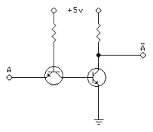
This AND gate seems a little more sensible! As it follows the rules of how NPN transistors work!
For example, the way transistors work (from what I know) is that NO CURRENT can flow through the N to N in NPN without the gate or the "P" in NPN having a current applied to it. So, like the picture to the left, when a current is applied to the gate(s), the connection is established, flowing from the left through both transistors to the OUT. [From what I know] both NPN and PNP gates work like this. But I don't think there is a way to STOP a current from flowing through the transistor by applying a current to the gate, or is there (like the about NOT gate transistor examples shows)? By this, I mean that for a NOT gate, to turn a 1 into a 0, (ONE into a ZERO), you'd have to somehow allow a gate to be DISABLED by applying a current to it, wouldn't you? And you would also have to allow a 0 to turn into a 1 as well; to have the current be ENABLED with no current or something (the boolean NOT gate would have to have one of its inputs register NO CURRENT, a binary 0 (ZERO), then would have to somehow let a current flow through the emitter to the collector to allow it to follow through the circuit to register as a 1 (eg. a NOT gate changing a ZERO (no current) into a ONE (current). So anyways, how would you produce a NOT gate with transistors? --
TAz69x 23:57, 16 April 2006 (UTC)reply
That picture describes relay logic. It does not explain how an electronic AND gate works. An electronic AND gate does not have two transistors in series. In fact, with NPN transistors it's easier to build a NOR gate, which has two or more transistors in parallel, and then to combine multiple NOR gates to make any kind of gate you like. Meanwhile, you might try looking at some
Texas Instruments data sheets, which contain excellent schematics of the gates' internal workings. An example of a
TTL hex inverter is
here (PDF). --
Heron 15:01, 15 April 2006 (UTC)reply
For example, a
relay (like a transistor but with an electromagnet + a moving switch) could be set up with a spring so that when an electrical current is applied to the electromagnet (the "gate"), it breaks the current of the switch, effectively making a NOT gate with a relay. For example, a constant current would be applied to the switch, and when a current hits the relay, a 1, the switch would be broken, with the result being a 0. But when a zero (no current) is applied to the relay, the switch would remain, giving a result of 1, effectively creating a NOT gate!
But transistors don't work like that. A transistor can't be SHUT-OFF WITH a CURRENT, can they? Is there a difference between NPN transistpors and PNP transistors? Can PNP transistors be SHUT-OFF with a current applied to the gate?, as opposed to NPN transistors where a current applied to the gate TURNS-ON the transistor current from emitter to collector.
Anyways, my real question was just how can a NOT gate be formed with transistors, diodes, and/or resistors. Any combination of the three things to create a NOT gate would be GREATLY appreciated, and most importantly, a DIAGRAM!!! Thanks. --
TAz69x 23:57, 16 April 2006 (UTC)reply
Real logic gates are much more complicated inside than simple teaching diagrams suggest, but here is a very simple way of building a NOT gate with a single transistor:
When input A is low, the base and emitter of transistor T1 are both at ground potential, so no current flows from A into the base, T1 stays off, and R2 pulls the output Y high. When input A is high, current flows into the base of T1 through R1, switching T1 on and pulling output Y low. Therefore, Y = not A. This is RTL (resistor-transistor logic) - not widely used, but easy to understand. --
Heron 14:51, 15 April 2006 (UTC)reply
Would you be able to draw a diagram in Paint then upload it? Sorry, but I don't quite understand that ASCII diagram. Thanks for trying though! The things that I don't understand are "VCC", "C", that strange little "B" beside that + sign, and "E".
Other than that, I think that |R1| and |R2| are resistors. But how do these work? When a current is applied, do they stop-it or reduce-it?, because I thought that a resistor reduced a current passing through possibly to the point of stopping it completely, or do these ones work differently than normal resistors??
And I was wondering, as I assume the "GND" means "GROUND", what the GROUND is in this diagram. From what I know, I always thought that "A" for example (or maybe Y?) would be the negative current of a "battery" for example passing through a wire, and that the "GROUND" would be a wire connecting to a "positive" terminal of a battery, thus creating a complete current. But is this what a GROUND really is, or what does a GROUND really do? And aside from that, is that what "GND" means in this diagram?
If you can draw the diagram using paint, can you show a duplication of the same picture, except the second picture(diagram drawing) showing the path that the current is taking, perhaps leading to and from a battery itself if possible, and/or a button along the diagram to show what "A" is. Because in the above ASCII diagram, I don't understand what most of the outlets are, or what path the current is taking. Perhaps one drawing being black or colored wires with red colored circutry, and the other picture a copy of the first one, with blue electricity showing arrows for its path or something. Thanks so much!
My view of the above diagram is:
- I think that "A" is input from the user or another part of the circuit, being a binary 1 (current) or a binary 0 (no current).
- And I think that Y is the output to the rest of the circuit, being an inverse from the "A" input (because the whole thing's a NOT gate), so if A=1,Y=0 and if A=0,Y=1.
- But in this process, I don't understand what those other lines are other than A or Y (if I have these two right at all!), such as what "GND" does,
- what that little "B" and
- "C" and
- "E" are/what they do,
- what "VCC" does or what it means, and
- what part the "resistors "R1" and "R2"" play in this diagram.
perhaps in addition to the above Paint diagram, you could draw one that shows step-by-step, what the electricity passing through the diagram would have happen to it as it hits each part of diagram. For example, (each number would be an individual picture, which would be a slightly altered copy of the one before it, but just advanced a bit with each step!): --
TAz69x 23:57, 16 April 2006 (UTC)reply
1 - the Paint drawing shows the input is coming from "A", (but has traveled no further yet!), the electricity is (for example) 5V and 0.2amps, "this" is what kind of things could provide the input, like the push of a button (for example!), and it is a "negative" current, starting from the "negative" source of a battery/power source (for example!)
2 - the input now hits the first |R1| and "this" happens to the electricity, at (for example) 0.1V now and 0.2amps
3 - now that the electricity is like "this" after hitting |R1| (for example, the current is now 0.1V or something)
4 - the current now hits this part of the transistor, and at 0.1V/0.2amps, "this" begins to happen, and (for example), if the current wasn't changed to 0.1V from 5V by the |R1| resistor, "this" would have happened instead), but anyways, this is what happened along with the |R1| resistor
5 - the electricity needs the "GND" for "this", and it does "this", and "this" is what happens to the current/other things
6 - the little "B" is for "this"
7 - the electricity now travels to the little "C" in the wire, and "this" happens, and the little "C" is meant to do "this"
8 - ...! --
TAz69x 23:57, 16 April 2006 (UTC)reply
this would be the PERFECT diagram/explanation for me! Please can you draw such a thing, I REALLY need this kind of graphical help to understand what this means. From the sounds of it, you have the intelligence/talent to explain to me how it works! This would be EXACTLY what I need to start understanding more about boolean logic and how it really works! Without it, I might never be able to jump from a partial understanding to a real-visual understanding of how the electricity travels and how it works! Thanks so much (and especially hopefully for the Paint diagram/explanation!!!) --
TAz69x 23:57, 16 April 2006 (UTC)reply
TTL NOT gateHere's a diagram that somebody else drew earlier. It's close enough. Ignore the transistor and resistor on the left, and imagine them replaced by resistor R1 from my ASCII drawing. The transistor on the right is T1 in my drawing. VCC means +5 V, and GND means ground. If you want to see the complete circuit, you can imagine the + terminal of a battery connected to +5 V and its - terminal connected to GND. The top terminal of the transistor is the collector (C). The bottom one is the emitter (E). The middle one, on the left, is the base (B). You called this the "gate", a term that does not apply to NPN transistors. R1 and R2 are, as you guessed, resistors. They are there to reduce the current that flows into the transistor; if they weren't there, the transistor would be destroyed. You are right about the meanings of A and Y, but this new drawing I found shows Y as .
Imagine you start with A at logic 0 (connected to ground). The transistor T1 is switched off, so it might as well not exist. The only component that does anything is R2. It connects the output to +5 V, making it a logic 1 (+5 V). 0 in, 1 out. If you don't connect the output to anything, then no current flows anywhere. If you connected the input of a second logic gate to the output Y, then a current would flow from +5 V, through R2 to Y, through the second logic gate to ground, through the battery, and back to +5 V, completing the circuit. There is no such thing as a "negative current" in this context. There is just current, with a specified direction and magnitude.
Now set the input A to logic 1 by connecting it to +5 V. You could do this with a piece of wire, a pushbutton, or another logic gate. Suppose R1 is 10,000 ohms. Before current starts to flow, B is at ground potential (0 volts). A is at +5 V, because we just connected it there. The voltage difference across R1 is therefore 5 V - 0 V = 5 V. By
Ohm's law, the current that flows through R1 is 5 V / 10,000 ohms = 0.5 milliamps. This current then flows from +5 V, through R1, into the base (B) of T1, out of its emitter (E) and down to ground, through the battery and back to +5 V, completing the circuit. This current causes things to happen inside T1, one of which is that the voltage of B rises to about 0.7 V, and this is what switches the transistor on.
By the magic of semiconductors, the current that we just sent into the base triggers a drop in resistance along the path inside T1 from collector (C) to emitter (E). The resistance inside the transistor is now small - let us assume, for the sake of simplicity, that it is zero. The circuit now behaves, as far as we are concerned, as if there were a piece of wire connecting C and E. A new current now flows from +5 V, through R2, through the imaginary piece of wire, to ground, through the battery and back to +5 V. The voltage at the top of R2 is +5 V, but at the bottom it is 0 V, because of our fictional piece of wire. The voltage difference across R2 is therefore +5 V - 0 V = 5 V. Suppose that R2 is 1,000 ohms. Using Ohm's law again, the current through R2 is 5 V / 1,000 ohms = 5 milliamps. So, to summarise, we have fed in a current of 0.5 milliamps through R1 and it has triggered a new current, ten times larger, through R2. This magification of current enables the output of the circuit to drive the inputs of several other logic gates, if we want it to - this is "cascading". At the same time, the voltage at A has gone from 0 V to +5 V (logic 0 to logic 1) while the voltage on Y has done the opposite. Thus, we have built an inverter.
As you are not experienced in electronics, you might find that this explanation assumes too much knowledge, but to explain everything from first principles would require an entire text book. Wikipedia has not yet replaced all text books, I'm afraid. If you need more basic tuition, it might be better to ask specific, shorter questions at the
Reference Desk. --
Heron 21:40, 15 April 2006 (UTC)reply
That was amazing! I can't believe how well you wrote that, it REALLY helps! (gives Heron the Hero a big kiss). So, as I understand it, when the T1 transistor is NOT on, the current from A (logic 0) would be nonexistent, keeping the base of T1 off and removing the "wire", but another current from the top Vcc (+5v) would proceed on through to Y, as a Logic 1 now, effectively turning a logic 0 from A into a logic 1 from Y. --
TAz69x 23:57, 16 April 2006 (UTC)reply
Yes. I'm glad I haven't confused you yet. --
Heron 20:33, 16 April 2006 (UTC)reply
But when the A logic 1 turns on the base and turns on T1 creating our piece of "wire", then the ground is then exposed, so the current coming from Vcc (+5v) would ignore Y and proceed through T1 to the ground instead, because of our "fictional" piece of wire repesented by T1 there. And thus Y would effectively be a "no/little current" logic 0. --
TAz69x 23:57, 16 April 2006 (UTC)reply
Yes, although it is possible for current to flow in to Y from an external source, and then to ground through the "wire". You can use this fact if you want a logic 0 on the Y output to switch on a (very small) light bulb. You connect one end of the light bulb to Vcc and the other end to Y. When T1 switches on, Y effectively becomes ground, so current flows from Vcc, through the bulb and T1 to ground, and makes the bulb light. --
Heron 20:33, 16 April 2006 (UTC)reply
Because to complete our circuit here, the Vcc would avoid Y and go to Ground from Vcc instead (effectively + to - terminal of our battery powering this circuit), for the A=1, Y=0 logic state. And when A=0, the T1 is off, but the current comes from Vcc anyways, and since it's not grounded like A=1, then it's able to continue onto Y. --
TAz69x 23:57, 16 April 2006 (UTC)reply
I hope I've got this right, because it kinda makes sense here in my head right now. So I as understand it, to make a NOT gate, all you have to do is use a transistor to expose a Ground to our constant current (Vcc), to lead it away from Y whenever you want Y to be logic 0. Thanks again so much! Please tell me any mistakes I've made. --
TAz69x 23:57, 16 April 2006 (UTC)reply
Yes, that's it. Don't forget that this is only one type of logic circuit, called resistor-transistor logic (RTL), which is not used much nowadays (except for switching on very small light bulbs) but is the easiest to explain. There are several other types,
CMOS and
TTL being the main ones in use today. One of the problems of RTL is that those resistors R1 and R2 get slightly warm and waste power. CMOS and TTL use more complex circuitry to reduce that waste and also to make everything work faster.
Finally, as a substitute for that kiss, will you do me the favour of signing your comments on talk pages? It is standard Wikipedia practice. You can do it easily by adding two hyphens and then four tildes at the end of your comment, like this: --~~~~. The software will replace the tildes with your user name and the date and time. This makes it easier for third parties to follow the discussion. --
Heron 20:33, 16 April 2006 (UTC)reply
That's great! I had another question. So where does Y go to? I was just wondering why the current from Vcc would avoid Y and go to the Ground instead. Does Y not lead to the + or - terminal of the battery? Because I'm imagining a huge circuit in my mind that this logic gate is part of, but I don't know where Y would eventually lead to at the end of its trip. Wouldn't it somehow have to eventually lead to the + or - terminal of a battery for a current from Vcc to ever want to travel down it? Thanks again! --
TAz69x 23:57, 16 April 2006 (UTC)reply
Heron, are you still there? I was wondering if all of this clutter was keeping you from seeing my last question. Anyways, hopefully you see it and can answer it! Thanks! --
TAz69x 14:55, 17 April 2006 (UTC)reply
Where Y goes to depends on what you are using the logic gate for. You could be using it to switch on a light bulb, in which case see my answer about eight paragraphs earlier. Perhaps you missed it in the clutter. My comment on this subject was timestamped 20:33, 16 April 2006 (UTC). Alternatively, you could connect Y to the input of a second logic gate. Imagine that gate has multiple inputs, one of which is called P, and you connect Y to P. When Y is high, a current flows from Vcc, through R2, ignores T1 and flows to Y instead, then into P, into the base of a transistor in the second gate, switching that transistor on, and then out of the transistor's emitter to ground. When Y is low, on the other hand, current flows through R2 and T1 to ground. No current flows out of Y into P because current only flows from a higher voltage to a lower one. Y is at 0 volts, and so is P, so no current flows and the second logic gate is not activated.
By the way, to avoid losing ourselves in the clutter, can we put all future comments in chronological order at the end of this section, please? --
Heron 20:24, 17 April 2006 (UTC)reply
Aside from my above question, I was hoping that these questions could be answered as well if possible:
- Are there any definitive sites or articles here or anywhere else that show cascading as was mentioned above? What cascading is, how it works, how it can be implemented in an
integrated circuits, etc. Preferably sites/articles that allow amateurs and professionals alike to understand the material?
The circuit I just drew is an example of a logic circuit that can be cascaded. You just connect the Y from one gate to the A of the next gate. As long as you choose the right values for R1 and R2, it will work. The point of it is that you only need to feed a small current into the A of the first gate to operate the entire cascade. Cascading isolates the inputs from the internal circuitry and from the outputs , so that the current flowing into A is always the same regardless of the complexity of the rest of the circuit. --
Heron 15:16, 15 April 2006 (UTC)reply
- Are there any sites/articles that show more in-depth boolean logic circuit designs (eg. addition, subtraction, multiplication, etc.). Graphically what they may look like, tips for designing, etc.
- Are there any programs for windows that allow you to play around with boolean logic designs and create some integrated circuit designs graphically?
- Are there any sites/articles that explain how integrated circuits work with the electricity passing through them? Eg. How is it that for an arithmetic unit for example, how an integrated circuit keeps from some transistors/boolean-gates from having the electricity moving through them faster than other parts. For example, you have a 4-bit binary adder, and the numbers on the right begin passing through the adders and answer parts before other parts of the adder are able to come up with an answer. Are there ways that integrated circuits are designed that they can "wait" for an answer, by waiting until ALL FOUR out-ports of the integrated circuit adder have an answer ready? And if so, how could this be implementer, that an integrated circuit could be designed so that parts of it can wait until all necessary parts which are to give an answer for example have all finished up before passing the answer to a new part of the integrated circuit for example? Perhaps capacitors are used to temorarily store the answers of individual components of the chip until they are all full and can be passed on to the next part of the integrated circuit? And if so, how could this be implemented in the integrated circuit with transistors for example so that this would work? Maybe an article/site that explains this (preferably to amateurs as well!).
ALUs generally use
pipelined logic, which contains
flip-flops to store intermediate results. This sort of thing should be discussed under
sequential logic. --
Heron 15:07, 15 April 2006 (UTC)reply
- Are there any sites/articles that show how to create boolean logic-gates with transistors, diodes, and/or resistors? I was wondering how these gates can be implemented using physics objects instead of just conceptually on paper.
Please feel free to answer ANY ONE of these questions at any time, but please answer the first NOT GATE first if possible! But if not and you have an answer to any of the other ones, then please don't hesitate to answer one of the other ones! Thanks for your help!
The first "NOT GATE" in this talk section is not a NOT Gate, its a switch. — Preceding
unsigned comment added by
Daiyusha (
talk •
contribs) 07:01, 9 September 2016 (UTC)reply
I would recommend reading the logic family article. Your asking a very broad question because there are many different flavors of logic which differ on the physical components used.
Adam Y (
talk) 14:52, 19 May 2008 (UTC)reply
INHIBIT logic gate
what is a INHIBIT logic gate?
V8rik 22:34, 20 April 2006 (UTC)reply
A 2-input inhibit (INH) gate implements the function A ^ 'B (A XOR NOT B). As far as I can see, this is the same as XNOR.
Graham 08:10, 21 April 2006 (UTC)reply
Thanks
Graham for your reply!
V8rik 20:11, 25 April 2006 (UTC)reply
I know I'm very late to this particular conversation... but the INHIBIT gate I've been able to find is a 3-input AND gate with one of the inputs inverted (A AND B AND NOT C).
This reference uses a three input AND with inhibit, but the accompanying text seems to imply that any logic gate can be the basis for an "inhibit gate". For instance, an AND gate (A AND B) becomes an AND gate with inhibit (A AND B AND NOT C), where C is the inhibit line. I don't know what "the" INHIBIT gate would be for a three-input system, if there is one, but it seems to me that the two-input INHIBIT would be (A AND NOT B).
Urocyon 05:37, 17 April 2007 (UTC)reply
NAND gate
I would like to publicize the article
CMOS#Example: NAND gate which gives a clear physical layout of a NAND gate (The A and B inputs are implied; you would have to add metal layers to pads surrounding this gate). By the repeated application of the
Sheffer strokeoperator (NAND), it is possible to build up combinations of NANDs to yield the other logic gates, of course. --
Ancheta Wis 09:16, 28 April 2006 (UTC)reply
History
Does anyone have any references to the historical development of the electronic circuit symbols and language? When did it start, who started using drawings to do a combination of logic and electronics? etc. These would be good issues address in the article.
Sholto Maud 10:58, 6 June 2006 (UTC)reply
A little late to the party here, but ...
Symbols for electrical circuits were first used in the late 19th century. I can't say precisely when symbols for logic functions first appeared, but it was prior to 1956. The MIL-STD-806B revision, for example, was issued in 1962. From the Foreword for IEEE Std 91-1984:
"This revision is the result of a continuing activity to arrive at a useful notation to permit free interchange of information on the design of binary-operated controls and systems. It is the latest step in a program that began in 1956 within the IEEE to develop a comprehensive single standard, consistent with ongoing developments in technology and logic symbology, from several ad hoc, industry, military, and international standards. In 1960, an ad hoc group on logic diagram graphic symbols was formed within the American National Standards Institute in order to develop a draft American Standard. In 1961, this committee became a permanent subcommittee, Y32.14, of the Graphic Symbols Committee, Y32, under the cosecretariat of ASME and IEEE. Its work resulted in the publication of IEEE Std 91-1962 (ANSI Y32.14-1962), adopted in 1965 by the US Navy. The subcommittee was reorganized in 1969 to prepare a new draft standard that would have broader acceptance and be in accord with the developments within the International Electrotechnical Commission (IEC). ANSI/IEEE Std 91-1973 (Y32.14-1973) subsequently received approval from ANSI, and the US Department of Defense, and was substantially compatible with IEC Pub 117-15, Recommended Graphical Symbols: Binary Logic Elements. Since 1977 the preparing committee, IEEE SCC 11.9, has worked closely with IEC Technical Committee 3 to prepare major new revisions of this standard and IEC Pub 617, Part 12 (the successor to Pub 117, Part 15)."
There is a summary table at the end of IEEE Std 91 that shows the progression of symbols over the years. — Preceding
unsigned comment added by
98.216.125.82 (
talk) 16:08, 15 August 2011 (UTC)reply
Congrats
Excelent article, very usefull. Thanks to all editors. --
201.6.161.117 04:56, 10 September 2006 (UTC)reply
Indeed. Unlike many articles I read, this one actually explains how the subject works, something that articles tend to miss. I learned a ton of info from reading this page. Good job! --The Prophet Wizard of the Crayon Cake 21:36, 28 September 2006 (UTC)reply
Resolved
neon bulb logic
I think it would be really nifty if this article on logic gates had (or linked to) a drawing/schematic for each known implementation of logic gates.
We have
ladder logic and some of the many kinds of transistor-based logic gates.
I want to add hydraulic "spool valve" logic gates and neon lamp logic gates.
The
neon lamp article mentions
"In the 1960s General Electric (GE), Signalite, and other firms made ... neon lamps for electronic uses. They even devised digital logic circuits, binary memories, and frequency dividers using neons."
I understand how to make logic gates out of transistors.
How is it possible to make logic gates out of neon bulbs?
With a bit of googling, I've found
a schematic for a 3 bulb sequential flasher/oscillator
[6],
and photographs of a neon bulb ring counter
[7].
Could some help me reverse-engineer a schematic for that ring counter,
or help me puzzle out some other logic circuit (NOT, NAND, NOR) using neons?
(Using neons, diodes, resistors, and capacitors -- but no integrated circuits or discrete transistors or relays).
The "neon logic" described above did not use simple neon lamps, but rather something similar to
electron tubes, that instead of being vacuum were filled with neon gas. Examples were counter circuits, where an input pulse triggered the discharge from one "counter segment" to the next "counter segment" through a cunning layout of the "anodes" "cathodes", and "trigger electrodes" that made up the counter segment. The electrodes were laid out in a ring, so the "last" electrode again triggered the "first" electrode and also outputted a pulse for the next counter tube. The neon light, of the currently ignited electrode could be seen from the outside, so these counter tubes worked as ring counters and indicators at the same time, they were used for atomic clocks. The principle behind it that the neon between the "anode" and "cathode" of the neon tube could be ignited using a separate "trigger electrode", much like a
thyristor. Once triggered the neon lamp staid ignited until the current flow was interrupted. Such a tubes were referred to as
decatrons[8]
I am not aware that circuits that used a OR or AND port structure were constructed with these kind of tubes, but it's possible. It's better to see the neon tube as a kind of "memory element" though.
Mahjongg (
talk) 11:27, 30 April 2008 (UTC)reply
NOR_gate has it's own article, while
NAND_gate points back to this article. Is there a NAND_gate article coming, or is the NOR_gate article going to be merged into this one? I would rather see a separate NAND article myself.
Ken6en 08:10, 30 October 2006 (UTC)
Oops, I see the problem...
NAND_Gate points to this article, and
NAND_gate is an existing article. I'll change all references to NAND_Gate back to NAND_gate.
Ken6en 08:14, 30 October 2006 (UTC)reply
Truth Table Values
Are the values of Not A and Not B transposed?
The article miss-represents the NOT gate. A not gate has 1 input and 1 output. The ouput is NOT the input. So if the input is 1 the output is 0. A two input not gate would have to have two outputs, one for each input.--
155.144.251.120 00:37, 11 January 2007 (UTC)reply
I created a new version of the symbol with only one input, but for some reason the author of the image has created a two-input version from a previously one-input version. OK to change? Well, maybe I should read the standard :)--
Wormsie 14:23, 25 September 2007 (UTC)reply
I went ahead and reverted the image with a comment. Hopefully he'll make a better one now.
Dicklyon 02:20, 26 September 2007 (UTC)reply
Neurons?
Should it not be added to the intro paragraph that logic gates can be formed out of several neurons? —Preceding
unsigned comment added by
140.247.44.93 (
talk) 19:34, 6 November 2007 (UTC)reply
Million-gate chip
Is there any chip commercially available with a million logic gates? I am not sure if the number of logic gates match the number of transistors.
[9]Anwar (
talk) 17:24, 10 May 2008 (UTC)reply
Yes, several
field-programmable gate array chips and other chips contain well over a million logic gates.
Each logic gate is built out of some integer number of transistors.
Most integrated circuits manufactured recently are built using
CMOS, using 2 transistors for a NOT gate, 6 transistors for a 3-in NAND gate, etc.
Counting transistors is a more objective method of measuring the size of an integrated circuit than counting logic gates, because many integrated circuits include a bunch of transistors outside of any recognizable logic gate, such as in
register file and
DRAM.
--
68.0.124.33 (
talk) 19:31, 2 October 2008 (UTC)reply
Relay Logic?
Is there a connection between what is known as
'relay logic' and the topics covered here? It seems that people are using on this page what looks similar to the diagrams used in relay logic. So, is relay logic some kind of basic ingredient to depicting logic gates?
Peeceepeh (
talk) 14:42, 30 June 2008 (UTC)reply
Relay logic is the implementation of logic gates in electromechanical relays, like in old telephone switching circuits and pinball machines.
Dicklyon (
talk) 16:20, 30 June 2008 (UTC)reply
74CBT3253 dual 4way transmission gate MUX with a pair of XOR like 74LVC2G86 makes a great ALU slice. 5 ohms and 250pS through, so cascades like a relay and may propagate several slices without ripple before needing a buffer. Or build same of qty3 DPDT relays with free XOR across coils. What makes transmission gates relevant to relays is the option to solve a prefixed chain of switches by series current. Only the critical path of propagation really cares if switched-through or driven-combinatorial. See also Manchester Carry, ignoring anything about precharged dominoes... Ken KD5ZXG 20230609
A, B, Q?
Why is the output of a logic gate usually named Q? --
Abdull (
talk) 20:37, 28 August 2008 (UTC)reply
No one knows. Most electronic terms no one really knows. They go back 80 - 100 years or more and into different languages. No one knows why Q, or even J/K for flip flops, or even Vcc/Vdd for power sources was used. Alot of universities claim to have invented most of them. Q is probably simply because it was meant to O for output , but O looks like binary zero, so they put a little mark on it and it eventually became Q.--
155.144.40.31 (
talk) 05:56, 1 September 2008 (UTC)reply
IMO its still recent history, searching a bit reveals the true reason behind it.
Daiyusha (
talk) 07:03, 9 September 2016 (UTC)reply
155, In "JK flip-flop", JK stands for the initials of the designer Jack Kilby. It was invented at Texas Instruments in Dallas. --
Ancheta Wis (talk | contribs) 02:42, 26 March 2014 (UTC)reply
Most probably Q is used instead of O (as in Output). However, O may be confused with 0, especially if hand-written, but Q resembles O and it is visually distinct from 0. I assume this is something similar with the fonts that distinguish between O and 0 by having the 0 slashed. But this is just a guess without a reference to back it up.
148.64.26.230 (
talk) 14:19, 6 August 2021 (UTC)Apassreply
When this article mentions that "diode logic... is an incomplete form of logic. ... To build a complete logic system, valves (vacuum tubes) or transistors can be used.",
by "complete" I think it means the same kind of "computation universal".
The "functional completeness" article seems to be about highly abstract "logical connectives" in formal logic -- is there some other article that focuses more on the various concrete devices that are "computation universal"?
However, the
functional completeness article is the closest thing Wikipedia has to this concept of "computation universal" that I know about, so -- until I find a better article -- I'm going to link that phrase in this article to the "functional completeness" article.
--
68.0.124.33 (
talk) 04:45, 14 September 2008 (UTC)reply
Actually, spread spectrum clocks have a well defined mean period. Note the word "mean" , a spread spectrum clock starts of as a simple crystal oscillator, (with a well defined period), then (very small) a pseudo random "jitter" is added to the clock flanks, but the mean period of the clock signal is still the same. The jitter is just added so the spectrum of the emitted RF signal is "smeared out", lowering the peaks i the emitted spectrum, to better comply with EMC regulations. Note that the total amount of emitted RF energy is roughly the same, only spread out over a bigger spectral area.
So all that really has to be added is the word "mean", and then the jitter is very small compared to the total period of the signal. January 2009 (UTC)
A better example may be a clock of an asynchronous serial bus, like SPI, or I2S, where the clock comes when it is needed, and in-between data transfers can hold still.
Mahjongg (
talk) 23:11, 13
Logic function table
I've made a new table for the logic functions. I put it in a template
here, as it seems to me that this could be useful for other pages.
I've put in links to the more obscure functions (implication, non-implication, etc). It seems to me that the current explanatory text under the table is a bit confused, especially as the
material implication is what is usually meant by AB, rather than
logical implication (=entailment). While the two are very closely related, the material implication is the logical connective that links values in a truth table.
Inductiveload (
talk) 02:32, 28 January 2009 (UTC)reply
Discrete logic?
What is discrete logic? This term currently redirect to logic gate, but it is not explained what it means. Thanks, --
Abdull (
talk) 23:31, 8 February 2010 (UTC)reply
Discrete logic is logic (built using discrete components, or using IC technology) that "contains" single (OR, AND, NOR or NAND) gates. In the past these were RTL, DTL or TTL gates built with discrete components, that is resistors, diodes and transistors. Lately the term is more often used to describe single gate IC's, like the 74LVC1G00, that contains a single NAND gate in a
SOT-23-5 package (which is normally used for transistors).
Mahjongg (
talk) 00:06, 9 February 2010 (UTC)reply
Symbols
I have made some minor edits correcting the "Symbols" section. As the chairman of IEEE SCC11.9 and U.S. delegate to IEC TC3 WG2 over the many years the respective standards were written and revised, I am quite certain of the accuracy, so please forgive my presumptuousness in editing directly. Feel free to contact me if you have any questions.
This article is very unclear. I opened it wondering what a logic gate is, and closed it with no greater understanding than I came with. It explains logic gates in great detail to those who already have an idea of what they are, but offer no insight to those who don't. —Preceding
unsigned comment added by
90.36.15.143 (
talk) 08:59, 16 August 2010 (UTC)reply
The basic idea behind logic gates is not revealed
The article does not reveal the fundamental idea behind logic gates at all; it does not show how logical functions are implemented by various electronic circuits.
Background (as it is written) is more suitable as an introductory part of
Logic family.
Circuit dreamer (
talk,
contribs,
email) 19:35, 7 April 2011 (UTC)reply
Can we create unit cell using logic gates which when stacked with itself can behave like Universal Turing Machine with head being single signal moving between cells? I am trying to implement Wolfram (2,3) UTM, but it works wrong — Preceding
unsigned comment added by
83.21.106.70 (
talk) 18:49, 8 March 2012 (UTC)reply
I am not sure what you mean by unit cell, however, both NOR and NAND gates are universal gates. As such, given enough of them one could construct every conceivable machine/algorithm. --
CyberXRef☎ 01:51, 24 March 2014 (UTC)reply
Symbols - "in practice"
There are a bunch of places such as in the symbols section where it says something along "In practice, these gates are built from combinations of simpler logic gates." (talking about XOR). This is a very misleading statement. "In practice" there are so many things that get considered that how it's actually implemented various wildly as to make that statement obsolete. Many times standard cell for XOR which would be used around (XOR2, XOR3, XOR4, etg..) as well depending on the requirements. There are simply way too many way these things are made to fit in one sentence "In practice, ...". --
CyberXRef☎ 02:13, 24 March 2014 (UTC)reply
In the same vein, anon 76... describes a De Morgan equivalent applied to a motor.
76, I would appreciate a diagram to illustrate your latest contribution. --
Ancheta Wis (talk | contribs) 01:05, 26 March 2014 (UTC)reply
DIN (and other obsolete) symbol standards
There have been some attempts to document obsolete DIN 40700 symbols in this article (retired in 1998). Although there may some who are fond of them, there are also some who are fond of a number of other obsolete standards. I think this article should confine itself to currently approved and active standards and not to the history of the evolution of those standards, which is extensive. Perhaps another article could take on that task.
I have consequently removed some inserted (and erroneous) material relating to the obsolete DIN standard, but added clarification regarding the current standard and retained a reference to another article for those who might be interested in the history of the last 40 years. — Preceding
unsigned comment added by
66.30.92.163 (
talk) 15:32, 21 April 2015 (UTC)reply
According to your edit, you reverted the page due to the fact that DIN 40700 has been superseded by DIN EN 60617. This is indeed true, but according to this German article defining the DIN EN 60617 standard, the only form of digital logic defined by this standard are various analog-digital encoders and decoders:
http://pcad-libs.embedders.org/rules/ref_617.pdf
As logic gates don't even seem to be defined in the standard that you've referenced, and it is a fact that the logic gates defined by the DIN 40700 standard continue to be relatively widely used today, I cannot see how it is beneficial for encyclopedic completeness to merely leave an obscure reference to the German Wikipedia.
For this reason I've reverted your revert for now, until we can reach a conclusion.
VladVP (
talk) 07:06, 22 April 2015 (UTC)reply
IEC 60617 (and its adopted editions) is in several parts. Part 12 is binary logic elements. pcad-libs.embedders.org is not an authoritative source regarding these standards, but as you can see on the first page of that document, it deals, in any case, with only the first 11 parts of IEC 60617, which are not relevant to this article. For German text, two sources for DIN EN 60617-12 are
http://www.beuth.de/en/standard/din-en-60617-12/13197268 and
http://www.techstreet.com/products/1068561 , but the authoritative text is the original IEC 60617-12 (in English and French).
Because it appears that you have been missing some essential information about both the IEC and IEEE standards, I am reverting your edits to the original corrections I made.
If you have further questions, I would be happy, as a member of the IEC working group and as chairman of the U.S. working group during the time these standards were written, to answer them prior to any further edits. - Tom Smith — Preceding
unsigned comment added by
66.30.92.163 (
talk) 13:32, 22 April 2015 (UTC)reply
I agree with your view that the logic gate symbols defined by the DIN 40700 standard are largely obsolete, but simply removing information regarding them because of such an objective opinion cannot possibly be justifiable. As this article deals with logic gates, according to
Wikipedia:Relevance including information about a standard that has possessed notable significance within the electronics industry for several decades, and continues to do so to a lesser degree even today would be absolutely essential; whether alongside current industry standards or not.
In your first entry, you also claim the the edits you reverted contained erroneous information. The proper steps to take to resolve such an issue should be to make a new edit replacing the erroneous information, as opposed to making large reverts containing information that was implied sufficiently correct.
I propose a compromise between presenting the DIN gates alongside contemporary digital logic symbols, and making an unsatisfying interwiki link to the German Wikipedia. According to you, the DIN gates are historical, and should be presented as something historical, and as such I believe that this topic belongs in the
History and development section of the article.
I will refrain from making further edits regarding this topic, in order to prevent sparking an
edit war.
By all means, let's not engage in an edit war. Please understand that I have many flaws, but I do happen to be an expert on this matter, and I can number on the fingers of one hand the world's other experts, including the Dutch chairman of the IEC working group and its two German delegates.
The subject of this article is "Logic gate", and symbols are an ancillary (some might say intrusive) topic. As such,
History and development has to do with the evolution of logic gates, not symbols.
Should you choose to undertake a project to trace the history of these symbols and document that in a separate article, understand that that history does not lie only (or largely) in Germany. The existing standards are the result of the evolution of many disparate practices from many sources into one agreed world-wide practice. I refer you to the topic "History" above. A proper treatment of the subject would take that into account, and you would have a considerable amount of reading to do to understand all of that. However, I'm not sure it would be of much interest to anyone, and very possibly not worth the effort. Perhaps your purposes would be better served by editing the aforementioned German Wiki, which is where most of the interest might lie anyway.
For your information, by the way, there is not and never has been a standard "US ANSI 91-1984". [Thanks Ancheta Wis] — Preceding
unsigned comment added by
66.30.92.163 (
talk) 16:45, 22 April 2015 (UTC)reply
@
66.30.92.163, As an editor with an interest in this article, the sentence above, For your information, by the way, there is and never has been a standard "US ANSI 91-1984", is self-contradictory. One way to fix it up is 'For your information, by the way, there is [not] and never has been a standard "US ANSI 91-1984"'. Might this be what you mean? --
Ancheta Wis (talk | contribs) 11:10, 23 April 2015 (UTC)reply
Possibly plagiarized by Introduction to Digital Electronics
The text
here (starting at "In electronics, a NOT gate is more commonly called an inverter") appears to be taken from the text under the NOT gate in the table on this page. The copyright date of the book is 2014, and the text was on the Wikipedia page as of 2013, so it seems unlikely that Wikipedia is the guilty party. The book doesn't seem to provide a citation, nor be under an acceptable license -
furrykef (
Talk at me) 15:06, 18 March 2016 (UTC)reply
It wouldn't be the first time I'd been plagiarized (or those standards). I suppose it's a compliment. You could always provide a user review. :-) Note, though, that Wikipedia's rules are that "Work submitted to Wikipedia can be edited, used, and redistributed — by anyone — subject to certain terms and conditions." The text was added to this Wikipedia article at 03:01, 19 June 2010, to be exact. -Tom — Preceding
unsigned comment added by
73.47.87.95 (
talk) 23:09, 7 April 2016 (UTC)reply
Clarification of symbols for exclusive-OR and relatives
The symbols shown in the main article for exclusive-OR are defined in IEC 60617-12 and IEEE Std 91 as an exclusive-OR function only for two inputs (IEEE symbol 5.1-11, IEC symbol 12-27-09). There is no defined distinctive-shape symbol with more than two inputs for any function other than AND, OR, and their inverts.
For rectangular-shape symbols, there are a series of related symbols that have defined meanings with multiple inputs. The IEEE symbols listed below can be found as IEC symbols 12-27-01 through -09.
"=m" - IEEE symbol 5.1-6, m and only m function, of which "=1" (5.1-11) is a special case. The output is true iff exactly m inputs are true.
">=m" - IEEE symbol 5.1-5, threshold function, of which ">=1" (5.1-1) is a special case. The output is true iff at least m inputs are true.
">n/2" - IEEE symbol 5.1-7, majority function. The output is true iff more than half the inputs are true.
"=" - IEEE symbol 5.1-8, identity function. The output is true iff all inputs are in the same state.
"2k+1" - IEEE symbol 5.1-9, odd function. The output is true iff the number of true inputs is odd.
"2k" - IEEE symbol 5.1-10, even function. The output is true iff the number of true inputs is even. — Preceding
unsigned comment added by
73.47.87.95 (
talk) 16:52, 2 July 2016 (UTC)reply
Boolean algebra notation
I tried to add one of the OR boolean algebra symbols as listed on the
List of logic symbols page, but it was reverted as lacking a reference.
Currently AND gate lists , as notations but not . OR lists but not or . Should these alternative boolean algebra notations be listed? What if any ref is required?
Izyt (
talk) 18:51, 28 October 2016 (UTC)reply
and are, of course, both common, but I have never seen, and cannot find, any usage of to mean "OR" in mathematical notation. Perhaps you were thinking of C language syntax, in which it has a special additional (non-mathematical) meaning? — Preceding
unsigned comment added by
73.47.87.95 (
talk) 23:14, 7 November 2016 (UTC)reply
External links modified
Hello fellow Wikipedians,
I have just modified one external link on
Logic gate. Please take a moment to review
my edit. If you have any questions, or need the bot to ignore the links, or the page altogether, please visit
this simple FaQ for additional information. I made the following changes:
When you have finished reviewing my changes, you may follow the instructions on the template below to fix any issues with the URLs.
This message was posted before February 2018.
After February 2018, "External links modified" talk page sections are no longer generated or monitored by InternetArchiveBot. No special action is required regarding these talk page notices, other than
regular verification using the archive tool instructions below. Editors
have permission to delete these "External links modified" talk page sections if they want to de-clutter talk pages, but see the
RfC before doing mass systematic removals. This message is updated dynamically through the template {{
source check}} (last update: 5 June 2024).
If you have discovered URLs which were erroneously considered dead by the bot, you can report them with
this tool.
If you found an error with any archives or the URLs themselves, you can fix them with
this tool.
Please see the paragraph beginning ' 3. The concepts "positive-true logic" and "negative-true logic" ' in my section "Less esoteric usage and better explanation required" in
talk:Open collector.
Hedles (
talk) 15:35, 12 February 2020 (UTC)reply
Never mind. I see that Horowitz and Hill (1989) is cited in the Open collector article. But don't hold your breath on my finding my copy. If some other editor finds a suitable reference to back up the statements for the three articles, feel free to update the citations. --
Ancheta Wis (talk | contribs) 01:51, 13 February 2020 (UTC)reply
Great. Thank you, Ancheta. I have a copy of Horowitz and Hill from my Uni days but it must have been a much earlier edition than 1989 as I was well into my second decade of work by then. I'm in the midst of a clear out of the very shelves where it might be, so I'll probably dig it out in the next few days. I don't expect such basics as this will have been a later addition. However, a web source would, of course, be preferable for Wikipedia, so if anybody comes up with anything resembling a trusted web source . . .
@
Hedles, the evilmadscientist post is describing
tri-state logic, meaning neither 0 nor 1, but rather a high-impedance state (not part of the logic at the moment, i.e. not applicable in a data-collection form, so that part of the machinery is not working on the subject or topic, i.e., don't care). It's the equivalent of
Lazy evaluation in software. -- 13:00, 14 February 2020 (UTC)
CMOS logic allows much higher
Fan-out than TTL (so scaling up beyond tabletop circuits and low-speed applications becomes more practical and less expensive). -- 13:13, 14 February 2020 (UTC)
IEEE Std 91/91a, IEEE Std 991, IEC 60617-12, and the IEEE Dictionary (compiled largely from IEEE standards) use and define the terms "positive logic convention", "negative logic convention", and "direct polarity indication", and those terms are used in this article. These all have to do, of course, with the relationship between physical signal levels and logic states. Those are defined in the same standards as "0-state", "1-state", "high (H) level", and "low (L)" level. An individual input/output is termed "active-high" (1=H) or "active-low" (0=H)— Preceding
unsigned comment added by
2601:193:407F:D797:3CBD:4A6E:A441:6E9C (
talk) 16:32, 22 March 2020 (UTC)reply
Logic families
I think this topic is duplicated in the article. I think that the Electronic gates subsection should also be split into physical manufacturing and overview of logic families. AXONOV(talk)⚑ 15:46, 24 December 2021 (UTC)reply
Universal logic gates-XOR/XNOR asymmetry in the table?
Hi there folks! Just wanted to open this thread to discuss a small change I made to the table in the
Universal logic gates section of the article.
The XOR gate built from NOR gates in the table is the one which, according to the
XOR gate article, "offers the advantage of a shorter propagation delay":
Whereas the XNOR gate built from NAND gates in the table was originally the one which, according to the
XNOR gate article, actually has more propagation delay:
I figured it would probably be more appropriate - from both the perspective of (a) the table consistently showing the version of the gate with less propagation delay, and (b) symmetry and duality between XNOR/XOR ↔ NAND/NOR - to instead have the table show this version of the XNOR gate built from NAND gates:
I imagine this was just a minor oversight, probably due to the filename of the last image being XNOR from NAND 2.svg, while none of the rest of the filenames have that 2 in them. However, I'm not an electronics expert by any means! So please feel free to revert my edit, if in fact there was some other underlying reason for this asymmetry of which I'm just not aware.
Nicola Tesla demonstrated AND gate functioning before anyone named in this article.
Perhaps the most noteworthy implication of Tesla’s radio-controlled automaton, however, was demonstration of the basic “AND-gate” function that would become an indispensable element of all subsequent electronic and computer logic. His inspiration for this concept reportedly came from studying the work of Victorian biologist and philosopher Herbert Spencer regarding the combined action of two or more nerves in the human body. Tesla’s original implementation employed two sets of transmitters and receivers operating on different radio frequencies to trigger a pair of detector relays. Both these relays had to close at the same time in order to energize a third, which in turn incremented a mechanical escapement driving a rotary switch to decode the command. Tesla’s dual-receiver design provided a relay-based AND-gate function that allowed the contacts of R3 to close only when both R1 and R2 were activated by their respective signals (digitally enhanced from US Patent No. 725,605, awarded 14 April 1903). I feel like Tesla should at least be mentioned as having made an AND gate first. I realize it was not a modern gate, however it did function just like a modern gate.
162.246.112.154 (
talk) 17:27, 21 April 2024 (UTC)reply
I'm pretty sure the idea of closing two switches to make something happen predates Tesla and the idea of requiring two things to happen to enable a third thing might well go back to the era of the pyramids. The abstratction of coincidence from a particular application and generaling it as a component of man other systems is the key point here. --
Wtshymanski (
talk) 23:16, 22 April 2024 (UTC)reply
This article is part of WikiProject Electronics, an attempt to provide a standard approach to writing articles about
electronics on Wikipedia. If you would like to participate, you can choose to edit the article attached to this page, or visit the
project page, where you can join the project and see a list of open tasks. Leave messages at the
project talk pageElectronicsWikipedia:WikiProject ElectronicsTemplate:WikiProject Electronicselectronic articles
This article is within the scope of WikiProject Computing, a collaborative effort to improve the coverage of
computers,
computing, and
information technology on Wikipedia. If you would like to participate, please visit the project page, where you can join
the discussion and see a list of open tasks.ComputingWikipedia:WikiProject ComputingTemplate:WikiProject ComputingComputing articles
This article is within the scope of WikiProject Technology, a collaborative effort to improve the coverage of
technology on Wikipedia. If you would like to participate, please visit the project page, where you can join
the discussion and see a list of open tasks.TechnologyWikipedia:WikiProject TechnologyTemplate:WikiProject TechnologyTechnology articles
Wiki Education Foundation-supported course assignment
This article was the subject of a Wiki Education Foundation-supported course assignment, between 22 January 2020 and 14 May 2020. Further details are available
on the course page. Peer reviewers:
Wintersfire.
Skoch3 (
talk) 19:55, 7 January 2010 (UTC)Anthony, Larry, AND I changed the language explaining that all the gates can be constructed from either NAND or NOR gates. We wrote: "All other types of Boolean logic gates (i.e., AND, OR, NOT, XOR, XNOR) can be created from a suitable network of NAND gates. Similarly all gates can be created from a network of NOR gates. Historically, NAND gates were easier to construct from MOS technology and thus NAND gates served as the first pillar of Boolean logic in electronic computation."reply
NAND and NOR gates in NMOS or CMOS both look equally complex/simple. Are you sure you don't mean TTL, where the multi-emitter input allows NAND gates to be much simpler than NOR gates?
60.241.12.136 (
talk) 11:43, 8 July 2010 (UTC)reply
Resolved
section
The images are for the American standard for gate symbols. The European, which I belive is the real standard (approved by ISO/ANSI or something), standard looks different. An AND gate is a square with an
ampersand in it, OR is a square with >= 1 in it and so on. I couldn't find any pics for them though. :-(
asdfasdfsdf
The article mentions
Nikola Tesla having patented logic gates as US645576, but I looked up
that patent, "System of transmission of electrical energy", and it appears to describe a means of transmitting electricity through the air, but nothing to do with logic gates. I've taken the reference to that patent out of the article. --
Arteitle 19:51, Mar 7, 2004 (UTC)
The relevant patents are US 723,188 and US 725,605 granted in 1903. They were filed as one application in July 1900 but subsequently divided. I have added them to the text. Conception of the idea was at least as far back as 1896, '...I have an instinctive knowledge of the same...' Tesla said during the interference deposition for the patent, (US Patent Office Interference No 21,701, Systems of Signaling, Nikola Tesla vs. Reginald A. Fessenden, 1902, reply to question 9, August 5th 1902)--
Smark33021 21:32, 23 Dec 2004 (UTC)
I've looked at the patents and they are for a signalling system, not a logic gate. Can someone tell me what relevance these patents have to logic gates? There's no mention of a logic gate in the claims, and the signalling system seems to rely on signals at different times, not at the same time, to operate a receiver. I wish I could point to an example of an "and" function used before the dates of these patents, I'm pretty sure this pre-dates electronics in general - if nothing else the
Strowger switch must have had logic at least as complicated as an "and" gate and it was patented a decade earlier. --
Wtshymanski 02:31, 27 Apr 2005 (UTC)
I agree, the Tesla patents are describing a type of frequency-keying modulation scheme. There is no mention of logic circuits, nothing in the diagrams to even indicate how he would match patterns of frequency keyings. I believe the comment about Tesla should be delete.
DonPMitchell (
talk) 20:15, 21 August 2012 (UTC)reply
very misleading
I'm new here, so I don't want to make any changes. I shall note, however, that logic gates used in digital integrated circuitry do not operate in this manner. The author is conveying the idea that a logic gate either allows a signal to pass (in his diagram from left to right) or doesn't allow a signal to pass. While this seems sensible to the novice, it is not correct.
The reason that the author's conception of logic gate cannot be used in digital circuitry is that when a signal is not allowed to pass--for instance, if one transistor in his AND gate is OFF--the signal (technically the voltage level) on the OUT end of his logic gate is ambiguous, or "floating" in electrical engineering parlance.
I agree with you. The inaccuracy could be fixed in two ways: (1) delete the switch diagrams and the text that refers to them, or (2) correct the switch diagrams by adding pull-up resistors (as in open-collector logic) or complementary switches (as in CMOS and TTL logic) or adding loads to the circuits (as in relay logic). Option 2 sounds horribly complicated, so I am tempted to go for option 1. Anybody else care to comment? --
Heron 21:32, 5 Jul 2004 (UTC)
I take the point, but I'm not sure I agree. The diagrams are not meant to indicate how an actual logic gate necessarily works, but what it is doing in principle. I think that's a better intention for the article - to show how an AND function for example can be illustrated in a manner that is fairly intuitive to most people. Most people can understand the operation of simple switches, whereas the operation of a transistor is less clear to most. In addition, there are hundreds of ways to actually implement gates in real integrated circuits - a TTL circuit will differ from a CMOS, so which one would you use? None of them represent a single, "one true way" to make a gate, even if CMOS for example might be possibly the most usual way. Perhaps the wording should be altered to make it clear that the diagrams are only conceptual (though in terms of logic they could be built and would generate the truth tables given - so they are also practical in that sense). The article can provide links to the pages that deal with particular technologies, and those pages could include diagrams showing how logic gates are built with those technologies.
Graham 22:52, 5 Jul 2004 (UTC)
I just took a
chainsaw to the article and separated the content into a switch/relay logic section and a semiconductor logic section. This way, I hope to prevent any mistaken idea that the two types of logic might be interchangeable, whilst preserving the content that
user:Dysprosia painstakingly added. --
Heron 09:07, 6 Jul 2004 (UTC)
This site is awesome. That was my first post, and I certainly didn't expect responses!
Please let me share my perspective. A typical person has no idea how a digital circuit does the things it does, but a curious and intelligent person, when presented with the opportunity, would be eager to find out.
I believe an essential feature of a logic gate is that it is cascadable--the output of the logic gate is able to serve as an input to another logic gate. When a reader discovers this, and when he sees how switches/transistors can perform logic operations such as AND, his computer is no longer magical--it is merely complex. If a logic gate is treated as a device that obstructs or allows the flow of electricity from point A to point B, the idea of cascadability is lost, or at least postponed.
I understand the difficulties of treating this accurately. Many readers will not be familiar with concepts like voltage, current, and resistance. But I do think that an ideal writeup must convey the idea of cascadability somehow. I think I will concede that the logic gate currently in the writeup is pedagogically acceptable even without a pulldown resistor--technicalities could be covered in writeups on digital logic schemes (e.g. CMOS). My fundamental complaints are that the inputs and outputs are undefined and that it is unclear how the output will be used at the next logic stage.
A good point. Switches and relays are cascadable though, so it could easily be conveyed by that, with a note to the effect that it is important and applicable to digital solid state circuits too. By the way, great job Heron!
Graham 12:56, 6 Jul 2004 (UTC)
Thanks :-) I added a note on cascading semiconductor logic, but I haven't done the same job for relays yet. I have a feeling that this article is a sleeping giant, with the potential to turn into a "How Computers Work: from Babbage to Qubits" essay. If it starts to get out of hand, we may need to split it up. --
Heron 13:57, 6 Jul 2004 (UTC)
I think that should be resisted. The article is simply about the Logic Gate as a functional concept - it actually isn't about how they are implemented by particular technologies. There are better places for much greater expansion of that, which can link back here for those that need to know the fundamental principles. I see this as a foundation article - interested readers can follow links to other places to get more detail, or follow a link back here if they were overwhelmed by to much technicality.
Graham 23:40, 6 Jul 2004 (UTC)
I agree. I was stating a fear, not an intention. It would be good, though, to have a list of all the implementations we can think of, with links to the relevant articles. --
Heron 08:28, 7 Jul 2004 (UTC)
I agree. The concept of "cascadable" logic is key. And logic gates do *not*, in general, simply pass or not-pass a signal. Someone please make a nice picture that reflects reality better. (Or else I threaten to inflict my feeble efforts to draw them). --
DavidCary 05:57, 15 Jan 2005 (UTC)
I have added the following to try to clear up the issue:
It should be noted that semiconductor logic gates are not conductive in both directions, as the input signal acts as a 'trigger' to allow current out of the output, rather than allowing current straight through from input to output. However, the following mechanical varitions do show the basic priciples of the gates without detailing the precise internal workings. For information about how modern semiconductors really work, see
CMOS.--
Jjbeard 05:51, 25 December 2005 (UTC)reply
Yeah, this article has been for 5+ years failing to make the distinction between the ideal model and physical devices. The distinction is now made in the lead, but it still lacking a section on that. Presumably, the effort here was to describe just ideal logic gates that can implemented in many ways (not necessarily electronic), but there no article on
electronic logic gate (and the term is not really used), so this article should describe that stuff as well. Any textbook on microelectronics will do.
Tijfo098 (
talk) 18:50, 7 April 2011 (UTC)reply
Mmkay, I was wrong about
"electronic logic gate" not being a common expression. Perhaps a sub-article would be justified then.
Tijfo098 (
talk) 18:57, 7 April 2011 (UTC)reply
tri-state logic
Where is the tri-state article ?
This is clearly not the right article to talk about
tri-statetristate3-state logic gates (such as the 74356, the
74HC125, etc.). Is "
transmission gates" really the best place ?
Where in the encyclopedia is the right place ?
Looks like a separate article doesn't exist yet. I'd suggest
tristate logic should be the title. However, note that the term itself is inaccurate - tristate logic is not a three-state logic system at all (i.e. trinary), but just binary logic which can be connected or disconnected to e.g. a common bus line. While this ability is important in practical electronic logic systems, it's not really all that exciting - maybe a two or three line paragraph here would be sufficient.
Graham 21:53, 23 Dec 2004 (UTC)
Tri-State, or "Three State" gates belong in an article relating to bus logic. The purpose behind this is to allow multiple modules composed of logic gates and registers to share a common bus to connect to other modules. It could become part of an article on MUX gates as those can serve a similar function inside FPGAs/ASICs. They are also available as gates in the same packaging and logic families as any other logic type (TTL, CMOS, ECL, etc.)
72.8.4.74 (
talk) 16:49, 21 August 2013 (UTC)reply
Excellent. If the term is inaccurate, then this is an excellent opportunity for this encyclopedia to teach me a more accurate term by defining the inaccurate term as a redirect pointing to the more accurate term. And the more accurate term would be ... what ? --
DavidCary 05:57, 15 Jan 2005 (UTC)
Rightly or wrongly, it has always been called '3-state' or 'three-state' logic. Note that 'tri-state' is a registered trade-mark of
National Semiconductor (as pointed out in
this PDF datasheet, for example, and mentioned in
this comment on a book by Sid Katzen), so we should probably avoid using this as an article title. Everybody else (Texas Instruments, Fairchild, Philips etc.) calls it '3-state'. In the field of
multivalued logic, the term '3-value' is used to describe trinary logic.
[1] --
Heron 12:21, 15 Jan 2005 (UTC)
Correct. See, for example, the IEEE Dictionary, IEEE Std 91 symbol 3.3-8, and IEC 60617-12 symbol 12-09-08. —Preceding
unsigned comment added by
71.232.120.146 (
talk) 21:26, 8 June 2010 (UTC)reply
diagrams
Am I seeing things or are the 'alternate AND' and 'alternate OR' labels switched on the diagram? For example: De Morgan's law says that P AND Q = NOT ((NOT P) OR (NOT Q)), i.e. there is an OR gate in the 'alternate AND' gate and vice versa. Also, following the circuits visually, it looks like they are switched.
Varuna 22:22, 2005 Mar 10 (UTC)
Aha! I'm not the only one to think that. I'm going to switch the captions. --
Wtshymanski 16:38, 12 Apr 2005 (UTC)
Logic gates and quantum physics
I know that from several citations I've seen, that it is known that an "AND" gate will produce more heat than a "NOT" gate, because under
quantum theory, information is destroyed and is released as heat (information is a very weird property in quantum theory), whereas an "NOT" gate merely converts information. Would it be good to try to elaborate some of this issue here? --
Natalinasmpf 03:35, 19 Apr 2005 (UTC)
My opinion is not to clutter the article up with deeply theoretical and abstract ideas - put it in an article linked to
quantum theory but I think it has no place in a discussion of real-world logic. I'd like to see the cites - can you provide a link that explains this in terms accessible to a non-physicist? Since anything you can do with an OR gate you can do with enough ANDs and inverters, and the reverse, I don't really see the fundmental reason for this observation. --
Wtshymanski 19:45, 19 Apr 2005 (UTC)
Whoops, I meant a "NOT" gate, not an "OR" gate,. But logic gates in essence deal with logic itself - I think perhaps some mention about quantum theory (which is real-world, after all) because it entails what the nature of logic really is. And you may accomplish a function with a different setup, but the question in physics becomes, is it efficient? The theory goes that quantum logic gates must eliminate the wasted heat (as information is destroyed in an AND gate: two inputs produce an output where you cannot reverse back to deduce the input), else it would create inteference which is more of an issue for a quantum processor. Oh, I found this:
[2], it cites the heat produced from destroyed information. And this too
[3], this
[4], and this
[5]. All these cite the production of heat due to the fact information is destroyed (heat being a byproduct of electrical resistance being a secondary product, heat produced by information destruction is way more). (Oh some of the proposed improvised quantum gates to make up for the elimination of such gates are also trinary gates). --
Natalinasmpf 23:39, 19 Apr 2005 (UTC)
Natalinasmpf, I think explaining this "here" in Wikipedia would be good. But rather than "here" at
logic gate, I think
reversible computing is a better place. --
68.0.124.33 (
talk) 16:25, 8 January 2009 (UTC)reply
The real history
Somewhere, probably not on a Web page, there's got to be some real history of the logic gate. The Tesla and Stowger patents referred to in previous versions of this article do not claim anything I can see called a "logic gate" or a functional equal. A mechanical logical-AND function must go back at least as far as the first lock with a key in it. I don't think you can patent the idea of logic alone, but I'd be happier if someone cited a patent that had as a major claim the idea that logical functions can be performed automatically. It may not be patentable at all. Babbage's difference engine predates even Tesla. --
Wtshymanski 22:05, 19 May 2005 (UTC)reply
Somewhere? It was in the reference links! BTW, Andy Kessler and Leland Anderson both cite Tesla as the original. Twenty First Century Books publishers is a lesser link (but another one). If you cannot understand the patents nor the links ... do not remove the information just because you don't like the information. PLEASE provide a link or a book to refute these sources!.
PS, put in Babbage's machine if you feel like it ... I think it may be a good addition.:
The cited patents are for a signalling system, not for logic gates. None of the claims mention an electronic implementation of a logic function, possibly because Tesla would have considered this of no novelty and unpatentable. Surely the first nameless tinkerer who wired two knife-switches in series has as much claim to "inventing" an AND gate. I don't see the relevance of the cited patents to the claim that Tesla invented the AND gate. The "Twenty First Century" reference seems to be highly partisan in advocacy for Tesla and does not explain the relevance of the cited patents. I dispute the accuracy of the claim. My reference is the cited patents, which do not claim an AND gate. --
Wtshymanski 00:42, 21 May 2005 (UTC)reply
The cited patents are for a signalling system which contain logic gates. The patent description descibes electronic implementation of a logic function (eg.,
relays [which Tesla called controllers]). Tesla has several patent concerning ON/Off controllers. When the basic ectromechanical controller is activated, it opens or closes sets of circuits. See
Implementing the AND Logic Gate With Relays at this page on how Tesla used his controllers. The patent office prevented later inventors from patenting them later when they tried to patent the logic gates, because of Tesla's
prior art. As to the relevance of the cited patents, it contain the basic operation of logic gates.
If you dispute the claim's accuracy, can you find references to bolster your case? Reference include the cited patents, which do describe AND gates (as well as other resources and other patents [such as his
Teleautomation patents], not just "20th century books" or "wikipedia copies").
JDR 00:27, 20 September 2005 (UTC)reply
I came to this page investigating a claim from
this Subject Zero Science video, at around the minute mark, that Tesla invented the AND gate.
Why has this discussion been dead for 15 years? It seems to me that there's plenty of precedent to make the claim. Just because Tesla doesn't call it an "AND gate", and just because the concept existed in mathematical theory prior to the 1903 patent (see above), and just because he doesn't draw direct attention to it because to him it seemed obvious... doesn't mean he didn't establish the implementation in actuality.
Why are we leaving this uncredited? At the very least, there should be a mention of the discussion of Tesla's involvement, and its historical significance, on the Wiki page.
80.7.82.235 (
talk) 13:36, 20 October 2020 (UTC)reply
General Tidy Up
Right - Ive had a good hack at the article and have made the first section especially more readable. I have lined up all the switch digrams with the relevant truth table and have also put these next to the relevant paragraph, and put each one in its own little section (i know it makes the ToC longer, but hey) I've also uploaded a modified version ofthe Alternate AND/OR diagram to show the NAND/NOR (I hope dypsrosia doesn't mind) gates. Also, I have done an article on making
gates form NAND gates only, and uploaded shiny new blue jpgs of every gate and the NAND equivalent.
I've uploaded a new version of the little summary table thing (Truth2.jpg), and done pages for the XOR and XNOR gates (IC Pinouts and stuff), rather than for the logical process. These are now under
XOR_gate and
XNOR_gate. the XOR and XNOR articles both have updated headers giving directions.
This article also needs directions to those pages, perhaps when the other pages to do with the actual gates are done...
Also can someone do new versions of the rectangular symbols the present ones look a bit old and tatty...something like the 'military' symbols on this page. Also someonee might want to think about changin any links to the blue symbols to the military black and white ones if they would be better that way (so, for example NOT the ones in the diagrams on the
NAND_logic page, but the symbol at the top of the
XOR page maybe).
Maybe not as pretty, though. Just a thought... —
Omegatron 22:08, 23 January 2006 (UTC)reply
{Electronicaly}
"They are primarily implemented electronically but can also be constructed using electromagnetic relays, electronic diodes, fluidics, optical or even mechanical elements."
In this part I will delete "electronic diodes" because they are included formerly in "implemented electronically".
User:Vanished user 8ij3r8jwefi 15:41, 6 February 2006 (UTC)reply
Some problems
This article has a couple of problems that I hope to address here before editing the page if appropriate:
-Firstly, and most importantly, there is no real definition of a logic gate. Specifically it should be defined that it performs a logic operation on 1 or more inputs to create a single output. There is need to define the logic levels here. Then explain how inputs can be outputs of other gates. The switch analogy used here is completely misleading. It tends to suggest, especially for the NAND circuits, that 3 inputs are required, that is the two switches pressed and the electrical signal itself. It is important that nothing to do with electricity is used at all in defining logic gates, which are a logical concept. Having swithes arranged so that a circuit becomes closed when A and B switches are pressed does not make a logical gate.
-Background does not say why diode logic cannt be used for all gates. Nor are any examples given of how to make gates different ways (there are only misleading switch circuits).
-The tri state section implies tristate is merely to help designers. This is totally incorrect. Tristate greatly reduces the amount of circuity involved when many components (video cards, memory etc. connect to the same bus).
Anyway i'll be doing some edits soon so like to know what you all think.
a third set of symbols
occasionally i've come accross symbols with the bubbles on the inputs (e.g. a NAND gate would be drawn as an or symbol with a bublle on each input). The idea being that you keep the core symbols for thier logical function and use the bublles to indicate a lines active state (then if you have a bubble feeding a non-bubble or vice-versa you have located a potential design error).
Anyone else encountered theese and do you think we should mention them?
Plugwash 23:28, 12 February 2006 (UTC)reply
I agree and a while back I did add something to this effect in the symbols section. I feel it would be useful to enhance the disgram to include these, as it helps to reinforce what the text is saying. Bubbles on the inputs are very common, and are a useful design aid too.
Graham 02:12, 13 February 2006 (UTC)reply
Yes, they are useful, but I would suggest adding them in a new section called "De Morgan equivalent symbols" or something. Adding them next to the standard symbols would cause an information overload for most readers. --
Heron 13:15, 15 February 2006 (UTC)reply
XNOR
Am I the only one who refers to XNOR as XAND?
Harvestdancer 19:37, 3 April 2006 (UTC)reply
Yup. (seriously - probably not, but I've not heard that usage before)
Graham 02:09, 4 April 2006 (UTC)reply
Actually, I just did a Google Search. It turns out that while the usage is less common, people do refer to it as such.
I propose that we include it in the article, not as a separate term but list it as an alternate name for XNOR in the section on XNOR.
This NOT gate seems impossible! The way it shows the transistor anyways, as I don't believe that a CURRENT applied to the GATE of this transistor can actually SHUT-OFF the current flowing from the emitter to the collector
I was looking at this page, and I am rather new to
transistors and
boolean logic (about a few months to a year or so), and I was wondering how a
NOT gate can be made using transistors, much like the AND gates (below) are shown how to be made using transistors. From what I know, it's not possible, as is shown in the misleading pictures of the NOT gate on the Logic Gates page for example (the picture to the left), for transistors to be constantly on and SHUT-OFF with an electrical current applied to the gate (the "P" in NPN), or is it possible for a current applied to the GATE of a transistor (the A in the picture of the NOT gate to the left) to SHUT-OFF the current passing through the transistor? --
TAz69x 23:57, 16 April 2006 (UTC)reply
That's a picture of a pushbutton switch, not a transistor, and I'm not surprised that you find it unhelpful. So do I. IMO we should be describing how real gates work, not adding another layer of abstraction. --
Heron 14:29, 15 April 2006 (UTC)reply
This AND gate seems a little more sensible! As it follows the rules of how NPN transistors work!
For example, the way transistors work (from what I know) is that NO CURRENT can flow through the N to N in NPN without the gate or the "P" in NPN having a current applied to it. So, like the picture to the left, when a current is applied to the gate(s), the connection is established, flowing from the left through both transistors to the OUT. [From what I know] both NPN and PNP gates work like this. But I don't think there is a way to STOP a current from flowing through the transistor by applying a current to the gate, or is there (like the about NOT gate transistor examples shows)? By this, I mean that for a NOT gate, to turn a 1 into a 0, (ONE into a ZERO), you'd have to somehow allow a gate to be DISABLED by applying a current to it, wouldn't you? And you would also have to allow a 0 to turn into a 1 as well; to have the current be ENABLED with no current or something (the boolean NOT gate would have to have one of its inputs register NO CURRENT, a binary 0 (ZERO), then would have to somehow let a current flow through the emitter to the collector to allow it to follow through the circuit to register as a 1 (eg. a NOT gate changing a ZERO (no current) into a ONE (current). So anyways, how would you produce a NOT gate with transistors? --
TAz69x 23:57, 16 April 2006 (UTC)reply
That picture describes relay logic. It does not explain how an electronic AND gate works. An electronic AND gate does not have two transistors in series. In fact, with NPN transistors it's easier to build a NOR gate, which has two or more transistors in parallel, and then to combine multiple NOR gates to make any kind of gate you like. Meanwhile, you might try looking at some
Texas Instruments data sheets, which contain excellent schematics of the gates' internal workings. An example of a
TTL hex inverter is
here (PDF). --
Heron 15:01, 15 April 2006 (UTC)reply
For example, a
relay (like a transistor but with an electromagnet + a moving switch) could be set up with a spring so that when an electrical current is applied to the electromagnet (the "gate"), it breaks the current of the switch, effectively making a NOT gate with a relay. For example, a constant current would be applied to the switch, and when a current hits the relay, a 1, the switch would be broken, with the result being a 0. But when a zero (no current) is applied to the relay, the switch would remain, giving a result of 1, effectively creating a NOT gate!
But transistors don't work like that. A transistor can't be SHUT-OFF WITH a CURRENT, can they? Is there a difference between NPN transistpors and PNP transistors? Can PNP transistors be SHUT-OFF with a current applied to the gate?, as opposed to NPN transistors where a current applied to the gate TURNS-ON the transistor current from emitter to collector.
Anyways, my real question was just how can a NOT gate be formed with transistors, diodes, and/or resistors. Any combination of the three things to create a NOT gate would be GREATLY appreciated, and most importantly, a DIAGRAM!!! Thanks. --
TAz69x 23:57, 16 April 2006 (UTC)reply
Real logic gates are much more complicated inside than simple teaching diagrams suggest, but here is a very simple way of building a NOT gate with a single transistor:
When input A is low, the base and emitter of transistor T1 are both at ground potential, so no current flows from A into the base, T1 stays off, and R2 pulls the output Y high. When input A is high, current flows into the base of T1 through R1, switching T1 on and pulling output Y low. Therefore, Y = not A. This is RTL (resistor-transistor logic) - not widely used, but easy to understand. --
Heron 14:51, 15 April 2006 (UTC)reply
Would you be able to draw a diagram in Paint then upload it? Sorry, but I don't quite understand that ASCII diagram. Thanks for trying though! The things that I don't understand are "VCC", "C", that strange little "B" beside that + sign, and "E".
Other than that, I think that |R1| and |R2| are resistors. But how do these work? When a current is applied, do they stop-it or reduce-it?, because I thought that a resistor reduced a current passing through possibly to the point of stopping it completely, or do these ones work differently than normal resistors??
And I was wondering, as I assume the "GND" means "GROUND", what the GROUND is in this diagram. From what I know, I always thought that "A" for example (or maybe Y?) would be the negative current of a "battery" for example passing through a wire, and that the "GROUND" would be a wire connecting to a "positive" terminal of a battery, thus creating a complete current. But is this what a GROUND really is, or what does a GROUND really do? And aside from that, is that what "GND" means in this diagram?
If you can draw the diagram using paint, can you show a duplication of the same picture, except the second picture(diagram drawing) showing the path that the current is taking, perhaps leading to and from a battery itself if possible, and/or a button along the diagram to show what "A" is. Because in the above ASCII diagram, I don't understand what most of the outlets are, or what path the current is taking. Perhaps one drawing being black or colored wires with red colored circutry, and the other picture a copy of the first one, with blue electricity showing arrows for its path or something. Thanks so much!
My view of the above diagram is:
- I think that "A" is input from the user or another part of the circuit, being a binary 1 (current) or a binary 0 (no current).
- And I think that Y is the output to the rest of the circuit, being an inverse from the "A" input (because the whole thing's a NOT gate), so if A=1,Y=0 and if A=0,Y=1.
- But in this process, I don't understand what those other lines are other than A or Y (if I have these two right at all!), such as what "GND" does,
- what that little "B" and
- "C" and
- "E" are/what they do,
- what "VCC" does or what it means, and
- what part the "resistors "R1" and "R2"" play in this diagram.
perhaps in addition to the above Paint diagram, you could draw one that shows step-by-step, what the electricity passing through the diagram would have happen to it as it hits each part of diagram. For example, (each number would be an individual picture, which would be a slightly altered copy of the one before it, but just advanced a bit with each step!): --
TAz69x 23:57, 16 April 2006 (UTC)reply
1 - the Paint drawing shows the input is coming from "A", (but has traveled no further yet!), the electricity is (for example) 5V and 0.2amps, "this" is what kind of things could provide the input, like the push of a button (for example!), and it is a "negative" current, starting from the "negative" source of a battery/power source (for example!)
2 - the input now hits the first |R1| and "this" happens to the electricity, at (for example) 0.1V now and 0.2amps
3 - now that the electricity is like "this" after hitting |R1| (for example, the current is now 0.1V or something)
4 - the current now hits this part of the transistor, and at 0.1V/0.2amps, "this" begins to happen, and (for example), if the current wasn't changed to 0.1V from 5V by the |R1| resistor, "this" would have happened instead), but anyways, this is what happened along with the |R1| resistor
5 - the electricity needs the "GND" for "this", and it does "this", and "this" is what happens to the current/other things
6 - the little "B" is for "this"
7 - the electricity now travels to the little "C" in the wire, and "this" happens, and the little "C" is meant to do "this"
8 - ...! --
TAz69x 23:57, 16 April 2006 (UTC)reply
this would be the PERFECT diagram/explanation for me! Please can you draw such a thing, I REALLY need this kind of graphical help to understand what this means. From the sounds of it, you have the intelligence/talent to explain to me how it works! This would be EXACTLY what I need to start understanding more about boolean logic and how it really works! Without it, I might never be able to jump from a partial understanding to a real-visual understanding of how the electricity travels and how it works! Thanks so much (and especially hopefully for the Paint diagram/explanation!!!) --
TAz69x 23:57, 16 April 2006 (UTC)reply
TTL NOT gateHere's a diagram that somebody else drew earlier. It's close enough. Ignore the transistor and resistor on the left, and imagine them replaced by resistor R1 from my ASCII drawing. The transistor on the right is T1 in my drawing. VCC means +5 V, and GND means ground. If you want to see the complete circuit, you can imagine the + terminal of a battery connected to +5 V and its - terminal connected to GND. The top terminal of the transistor is the collector (C). The bottom one is the emitter (E). The middle one, on the left, is the base (B). You called this the "gate", a term that does not apply to NPN transistors. R1 and R2 are, as you guessed, resistors. They are there to reduce the current that flows into the transistor; if they weren't there, the transistor would be destroyed. You are right about the meanings of A and Y, but this new drawing I found shows Y as .
Imagine you start with A at logic 0 (connected to ground). The transistor T1 is switched off, so it might as well not exist. The only component that does anything is R2. It connects the output to +5 V, making it a logic 1 (+5 V). 0 in, 1 out. If you don't connect the output to anything, then no current flows anywhere. If you connected the input of a second logic gate to the output Y, then a current would flow from +5 V, through R2 to Y, through the second logic gate to ground, through the battery, and back to +5 V, completing the circuit. There is no such thing as a "negative current" in this context. There is just current, with a specified direction and magnitude.
Now set the input A to logic 1 by connecting it to +5 V. You could do this with a piece of wire, a pushbutton, or another logic gate. Suppose R1 is 10,000 ohms. Before current starts to flow, B is at ground potential (0 volts). A is at +5 V, because we just connected it there. The voltage difference across R1 is therefore 5 V - 0 V = 5 V. By
Ohm's law, the current that flows through R1 is 5 V / 10,000 ohms = 0.5 milliamps. This current then flows from +5 V, through R1, into the base (B) of T1, out of its emitter (E) and down to ground, through the battery and back to +5 V, completing the circuit. This current causes things to happen inside T1, one of which is that the voltage of B rises to about 0.7 V, and this is what switches the transistor on.
By the magic of semiconductors, the current that we just sent into the base triggers a drop in resistance along the path inside T1 from collector (C) to emitter (E). The resistance inside the transistor is now small - let us assume, for the sake of simplicity, that it is zero. The circuit now behaves, as far as we are concerned, as if there were a piece of wire connecting C and E. A new current now flows from +5 V, through R2, through the imaginary piece of wire, to ground, through the battery and back to +5 V. The voltage at the top of R2 is +5 V, but at the bottom it is 0 V, because of our fictional piece of wire. The voltage difference across R2 is therefore +5 V - 0 V = 5 V. Suppose that R2 is 1,000 ohms. Using Ohm's law again, the current through R2 is 5 V / 1,000 ohms = 5 milliamps. So, to summarise, we have fed in a current of 0.5 milliamps through R1 and it has triggered a new current, ten times larger, through R2. This magification of current enables the output of the circuit to drive the inputs of several other logic gates, if we want it to - this is "cascading". At the same time, the voltage at A has gone from 0 V to +5 V (logic 0 to logic 1) while the voltage on Y has done the opposite. Thus, we have built an inverter.
As you are not experienced in electronics, you might find that this explanation assumes too much knowledge, but to explain everything from first principles would require an entire text book. Wikipedia has not yet replaced all text books, I'm afraid. If you need more basic tuition, it might be better to ask specific, shorter questions at the
Reference Desk. --
Heron 21:40, 15 April 2006 (UTC)reply
That was amazing! I can't believe how well you wrote that, it REALLY helps! (gives Heron the Hero a big kiss). So, as I understand it, when the T1 transistor is NOT on, the current from A (logic 0) would be nonexistent, keeping the base of T1 off and removing the "wire", but another current from the top Vcc (+5v) would proceed on through to Y, as a Logic 1 now, effectively turning a logic 0 from A into a logic 1 from Y. --
TAz69x 23:57, 16 April 2006 (UTC)reply
Yes. I'm glad I haven't confused you yet. --
Heron 20:33, 16 April 2006 (UTC)reply
But when the A logic 1 turns on the base and turns on T1 creating our piece of "wire", then the ground is then exposed, so the current coming from Vcc (+5v) would ignore Y and proceed through T1 to the ground instead, because of our "fictional" piece of wire repesented by T1 there. And thus Y would effectively be a "no/little current" logic 0. --
TAz69x 23:57, 16 April 2006 (UTC)reply
Yes, although it is possible for current to flow in to Y from an external source, and then to ground through the "wire". You can use this fact if you want a logic 0 on the Y output to switch on a (very small) light bulb. You connect one end of the light bulb to Vcc and the other end to Y. When T1 switches on, Y effectively becomes ground, so current flows from Vcc, through the bulb and T1 to ground, and makes the bulb light. --
Heron 20:33, 16 April 2006 (UTC)reply
Because to complete our circuit here, the Vcc would avoid Y and go to Ground from Vcc instead (effectively + to - terminal of our battery powering this circuit), for the A=1, Y=0 logic state. And when A=0, the T1 is off, but the current comes from Vcc anyways, and since it's not grounded like A=1, then it's able to continue onto Y. --
TAz69x 23:57, 16 April 2006 (UTC)reply
I hope I've got this right, because it kinda makes sense here in my head right now. So I as understand it, to make a NOT gate, all you have to do is use a transistor to expose a Ground to our constant current (Vcc), to lead it away from Y whenever you want Y to be logic 0. Thanks again so much! Please tell me any mistakes I've made. --
TAz69x 23:57, 16 April 2006 (UTC)reply
Yes, that's it. Don't forget that this is only one type of logic circuit, called resistor-transistor logic (RTL), which is not used much nowadays (except for switching on very small light bulbs) but is the easiest to explain. There are several other types,
CMOS and
TTL being the main ones in use today. One of the problems of RTL is that those resistors R1 and R2 get slightly warm and waste power. CMOS and TTL use more complex circuitry to reduce that waste and also to make everything work faster.
Finally, as a substitute for that kiss, will you do me the favour of signing your comments on talk pages? It is standard Wikipedia practice. You can do it easily by adding two hyphens and then four tildes at the end of your comment, like this: --~~~~. The software will replace the tildes with your user name and the date and time. This makes it easier for third parties to follow the discussion. --
Heron 20:33, 16 April 2006 (UTC)reply
That's great! I had another question. So where does Y go to? I was just wondering why the current from Vcc would avoid Y and go to the Ground instead. Does Y not lead to the + or - terminal of the battery? Because I'm imagining a huge circuit in my mind that this logic gate is part of, but I don't know where Y would eventually lead to at the end of its trip. Wouldn't it somehow have to eventually lead to the + or - terminal of a battery for a current from Vcc to ever want to travel down it? Thanks again! --
TAz69x 23:57, 16 April 2006 (UTC)reply
Heron, are you still there? I was wondering if all of this clutter was keeping you from seeing my last question. Anyways, hopefully you see it and can answer it! Thanks! --
TAz69x 14:55, 17 April 2006 (UTC)reply
Where Y goes to depends on what you are using the logic gate for. You could be using it to switch on a light bulb, in which case see my answer about eight paragraphs earlier. Perhaps you missed it in the clutter. My comment on this subject was timestamped 20:33, 16 April 2006 (UTC). Alternatively, you could connect Y to the input of a second logic gate. Imagine that gate has multiple inputs, one of which is called P, and you connect Y to P. When Y is high, a current flows from Vcc, through R2, ignores T1 and flows to Y instead, then into P, into the base of a transistor in the second gate, switching that transistor on, and then out of the transistor's emitter to ground. When Y is low, on the other hand, current flows through R2 and T1 to ground. No current flows out of Y into P because current only flows from a higher voltage to a lower one. Y is at 0 volts, and so is P, so no current flows and the second logic gate is not activated.
By the way, to avoid losing ourselves in the clutter, can we put all future comments in chronological order at the end of this section, please? --
Heron 20:24, 17 April 2006 (UTC)reply
Aside from my above question, I was hoping that these questions could be answered as well if possible:
- Are there any definitive sites or articles here or anywhere else that show cascading as was mentioned above? What cascading is, how it works, how it can be implemented in an
integrated circuits, etc. Preferably sites/articles that allow amateurs and professionals alike to understand the material?
The circuit I just drew is an example of a logic circuit that can be cascaded. You just connect the Y from one gate to the A of the next gate. As long as you choose the right values for R1 and R2, it will work. The point of it is that you only need to feed a small current into the A of the first gate to operate the entire cascade. Cascading isolates the inputs from the internal circuitry and from the outputs , so that the current flowing into A is always the same regardless of the complexity of the rest of the circuit. --
Heron 15:16, 15 April 2006 (UTC)reply
- Are there any sites/articles that show more in-depth boolean logic circuit designs (eg. addition, subtraction, multiplication, etc.). Graphically what they may look like, tips for designing, etc.
- Are there any programs for windows that allow you to play around with boolean logic designs and create some integrated circuit designs graphically?
- Are there any sites/articles that explain how integrated circuits work with the electricity passing through them? Eg. How is it that for an arithmetic unit for example, how an integrated circuit keeps from some transistors/boolean-gates from having the electricity moving through them faster than other parts. For example, you have a 4-bit binary adder, and the numbers on the right begin passing through the adders and answer parts before other parts of the adder are able to come up with an answer. Are there ways that integrated circuits are designed that they can "wait" for an answer, by waiting until ALL FOUR out-ports of the integrated circuit adder have an answer ready? And if so, how could this be implementer, that an integrated circuit could be designed so that parts of it can wait until all necessary parts which are to give an answer for example have all finished up before passing the answer to a new part of the integrated circuit for example? Perhaps capacitors are used to temorarily store the answers of individual components of the chip until they are all full and can be passed on to the next part of the integrated circuit? And if so, how could this be implemented in the integrated circuit with transistors for example so that this would work? Maybe an article/site that explains this (preferably to amateurs as well!).
ALUs generally use
pipelined logic, which contains
flip-flops to store intermediate results. This sort of thing should be discussed under
sequential logic. --
Heron 15:07, 15 April 2006 (UTC)reply
- Are there any sites/articles that show how to create boolean logic-gates with transistors, diodes, and/or resistors? I was wondering how these gates can be implemented using physics objects instead of just conceptually on paper.
Please feel free to answer ANY ONE of these questions at any time, but please answer the first NOT GATE first if possible! But if not and you have an answer to any of the other ones, then please don't hesitate to answer one of the other ones! Thanks for your help!
The first "NOT GATE" in this talk section is not a NOT Gate, its a switch. — Preceding
unsigned comment added by
Daiyusha (
talk •
contribs) 07:01, 9 September 2016 (UTC)reply
I would recommend reading the logic family article. Your asking a very broad question because there are many different flavors of logic which differ on the physical components used.
Adam Y (
talk) 14:52, 19 May 2008 (UTC)reply
INHIBIT logic gate
what is a INHIBIT logic gate?
V8rik 22:34, 20 April 2006 (UTC)reply
A 2-input inhibit (INH) gate implements the function A ^ 'B (A XOR NOT B). As far as I can see, this is the same as XNOR.
Graham 08:10, 21 April 2006 (UTC)reply
Thanks
Graham for your reply!
V8rik 20:11, 25 April 2006 (UTC)reply
I know I'm very late to this particular conversation... but the INHIBIT gate I've been able to find is a 3-input AND gate with one of the inputs inverted (A AND B AND NOT C).
This reference uses a three input AND with inhibit, but the accompanying text seems to imply that any logic gate can be the basis for an "inhibit gate". For instance, an AND gate (A AND B) becomes an AND gate with inhibit (A AND B AND NOT C), where C is the inhibit line. I don't know what "the" INHIBIT gate would be for a three-input system, if there is one, but it seems to me that the two-input INHIBIT would be (A AND NOT B).
Urocyon 05:37, 17 April 2007 (UTC)reply
NAND gate
I would like to publicize the article
CMOS#Example: NAND gate which gives a clear physical layout of a NAND gate (The A and B inputs are implied; you would have to add metal layers to pads surrounding this gate). By the repeated application of the
Sheffer strokeoperator (NAND), it is possible to build up combinations of NANDs to yield the other logic gates, of course. --
Ancheta Wis 09:16, 28 April 2006 (UTC)reply
History
Does anyone have any references to the historical development of the electronic circuit symbols and language? When did it start, who started using drawings to do a combination of logic and electronics? etc. These would be good issues address in the article.
Sholto Maud 10:58, 6 June 2006 (UTC)reply
A little late to the party here, but ...
Symbols for electrical circuits were first used in the late 19th century. I can't say precisely when symbols for logic functions first appeared, but it was prior to 1956. The MIL-STD-806B revision, for example, was issued in 1962. From the Foreword for IEEE Std 91-1984:
"This revision is the result of a continuing activity to arrive at a useful notation to permit free interchange of information on the design of binary-operated controls and systems. It is the latest step in a program that began in 1956 within the IEEE to develop a comprehensive single standard, consistent with ongoing developments in technology and logic symbology, from several ad hoc, industry, military, and international standards. In 1960, an ad hoc group on logic diagram graphic symbols was formed within the American National Standards Institute in order to develop a draft American Standard. In 1961, this committee became a permanent subcommittee, Y32.14, of the Graphic Symbols Committee, Y32, under the cosecretariat of ASME and IEEE. Its work resulted in the publication of IEEE Std 91-1962 (ANSI Y32.14-1962), adopted in 1965 by the US Navy. The subcommittee was reorganized in 1969 to prepare a new draft standard that would have broader acceptance and be in accord with the developments within the International Electrotechnical Commission (IEC). ANSI/IEEE Std 91-1973 (Y32.14-1973) subsequently received approval from ANSI, and the US Department of Defense, and was substantially compatible with IEC Pub 117-15, Recommended Graphical Symbols: Binary Logic Elements. Since 1977 the preparing committee, IEEE SCC 11.9, has worked closely with IEC Technical Committee 3 to prepare major new revisions of this standard and IEC Pub 617, Part 12 (the successor to Pub 117, Part 15)."
There is a summary table at the end of IEEE Std 91 that shows the progression of symbols over the years. — Preceding
unsigned comment added by
98.216.125.82 (
talk) 16:08, 15 August 2011 (UTC)reply
Congrats
Excelent article, very usefull. Thanks to all editors. --
201.6.161.117 04:56, 10 September 2006 (UTC)reply
Indeed. Unlike many articles I read, this one actually explains how the subject works, something that articles tend to miss. I learned a ton of info from reading this page. Good job! --The Prophet Wizard of the Crayon Cake 21:36, 28 September 2006 (UTC)reply
Resolved
neon bulb logic
I think it would be really nifty if this article on logic gates had (or linked to) a drawing/schematic for each known implementation of logic gates.
We have
ladder logic and some of the many kinds of transistor-based logic gates.
I want to add hydraulic "spool valve" logic gates and neon lamp logic gates.
The
neon lamp article mentions
"In the 1960s General Electric (GE), Signalite, and other firms made ... neon lamps for electronic uses. They even devised digital logic circuits, binary memories, and frequency dividers using neons."
I understand how to make logic gates out of transistors.
How is it possible to make logic gates out of neon bulbs?
With a bit of googling, I've found
a schematic for a 3 bulb sequential flasher/oscillator
[6],
and photographs of a neon bulb ring counter
[7].
Could some help me reverse-engineer a schematic for that ring counter,
or help me puzzle out some other logic circuit (NOT, NAND, NOR) using neons?
(Using neons, diodes, resistors, and capacitors -- but no integrated circuits or discrete transistors or relays).
The "neon logic" described above did not use simple neon lamps, but rather something similar to
electron tubes, that instead of being vacuum were filled with neon gas. Examples were counter circuits, where an input pulse triggered the discharge from one "counter segment" to the next "counter segment" through a cunning layout of the "anodes" "cathodes", and "trigger electrodes" that made up the counter segment. The electrodes were laid out in a ring, so the "last" electrode again triggered the "first" electrode and also outputted a pulse for the next counter tube. The neon light, of the currently ignited electrode could be seen from the outside, so these counter tubes worked as ring counters and indicators at the same time, they were used for atomic clocks. The principle behind it that the neon between the "anode" and "cathode" of the neon tube could be ignited using a separate "trigger electrode", much like a
thyristor. Once triggered the neon lamp staid ignited until the current flow was interrupted. Such a tubes were referred to as
decatrons[8]
I am not aware that circuits that used a OR or AND port structure were constructed with these kind of tubes, but it's possible. It's better to see the neon tube as a kind of "memory element" though.
Mahjongg (
talk) 11:27, 30 April 2008 (UTC)reply
NOR_gate has it's own article, while
NAND_gate points back to this article. Is there a NAND_gate article coming, or is the NOR_gate article going to be merged into this one? I would rather see a separate NAND article myself.
Ken6en 08:10, 30 October 2006 (UTC)
Oops, I see the problem...
NAND_Gate points to this article, and
NAND_gate is an existing article. I'll change all references to NAND_Gate back to NAND_gate.
Ken6en 08:14, 30 October 2006 (UTC)reply
Truth Table Values
Are the values of Not A and Not B transposed?
The article miss-represents the NOT gate. A not gate has 1 input and 1 output. The ouput is NOT the input. So if the input is 1 the output is 0. A two input not gate would have to have two outputs, one for each input.--
155.144.251.120 00:37, 11 January 2007 (UTC)reply
I created a new version of the symbol with only one input, but for some reason the author of the image has created a two-input version from a previously one-input version. OK to change? Well, maybe I should read the standard :)--
Wormsie 14:23, 25 September 2007 (UTC)reply
I went ahead and reverted the image with a comment. Hopefully he'll make a better one now.
Dicklyon 02:20, 26 September 2007 (UTC)reply
Neurons?
Should it not be added to the intro paragraph that logic gates can be formed out of several neurons? —Preceding
unsigned comment added by
140.247.44.93 (
talk) 19:34, 6 November 2007 (UTC)reply
Million-gate chip
Is there any chip commercially available with a million logic gates? I am not sure if the number of logic gates match the number of transistors.
[9]Anwar (
talk) 17:24, 10 May 2008 (UTC)reply
Yes, several
field-programmable gate array chips and other chips contain well over a million logic gates.
Each logic gate is built out of some integer number of transistors.
Most integrated circuits manufactured recently are built using
CMOS, using 2 transistors for a NOT gate, 6 transistors for a 3-in NAND gate, etc.
Counting transistors is a more objective method of measuring the size of an integrated circuit than counting logic gates, because many integrated circuits include a bunch of transistors outside of any recognizable logic gate, such as in
register file and
DRAM.
--
68.0.124.33 (
talk) 19:31, 2 October 2008 (UTC)reply
Relay Logic?
Is there a connection between what is known as
'relay logic' and the topics covered here? It seems that people are using on this page what looks similar to the diagrams used in relay logic. So, is relay logic some kind of basic ingredient to depicting logic gates?
Peeceepeh (
talk) 14:42, 30 June 2008 (UTC)reply
Relay logic is the implementation of logic gates in electromechanical relays, like in old telephone switching circuits and pinball machines.
Dicklyon (
talk) 16:20, 30 June 2008 (UTC)reply
74CBT3253 dual 4way transmission gate MUX with a pair of XOR like 74LVC2G86 makes a great ALU slice. 5 ohms and 250pS through, so cascades like a relay and may propagate several slices without ripple before needing a buffer. Or build same of qty3 DPDT relays with free XOR across coils. What makes transmission gates relevant to relays is the option to solve a prefixed chain of switches by series current. Only the critical path of propagation really cares if switched-through or driven-combinatorial. See also Manchester Carry, ignoring anything about precharged dominoes... Ken KD5ZXG 20230609
A, B, Q?
Why is the output of a logic gate usually named Q? --
Abdull (
talk) 20:37, 28 August 2008 (UTC)reply
No one knows. Most electronic terms no one really knows. They go back 80 - 100 years or more and into different languages. No one knows why Q, or even J/K for flip flops, or even Vcc/Vdd for power sources was used. Alot of universities claim to have invented most of them. Q is probably simply because it was meant to O for output , but O looks like binary zero, so they put a little mark on it and it eventually became Q.--
155.144.40.31 (
talk) 05:56, 1 September 2008 (UTC)reply
IMO its still recent history, searching a bit reveals the true reason behind it.
Daiyusha (
talk) 07:03, 9 September 2016 (UTC)reply
155, In "JK flip-flop", JK stands for the initials of the designer Jack Kilby. It was invented at Texas Instruments in Dallas. --
Ancheta Wis (talk | contribs) 02:42, 26 March 2014 (UTC)reply
Most probably Q is used instead of O (as in Output). However, O may be confused with 0, especially if hand-written, but Q resembles O and it is visually distinct from 0. I assume this is something similar with the fonts that distinguish between O and 0 by having the 0 slashed. But this is just a guess without a reference to back it up.
148.64.26.230 (
talk) 14:19, 6 August 2021 (UTC)Apassreply
When this article mentions that "diode logic... is an incomplete form of logic. ... To build a complete logic system, valves (vacuum tubes) or transistors can be used.",
by "complete" I think it means the same kind of "computation universal".
The "functional completeness" article seems to be about highly abstract "logical connectives" in formal logic -- is there some other article that focuses more on the various concrete devices that are "computation universal"?
However, the
functional completeness article is the closest thing Wikipedia has to this concept of "computation universal" that I know about, so -- until I find a better article -- I'm going to link that phrase in this article to the "functional completeness" article.
--
68.0.124.33 (
talk) 04:45, 14 September 2008 (UTC)reply
Actually, spread spectrum clocks have a well defined mean period. Note the word "mean" , a spread spectrum clock starts of as a simple crystal oscillator, (with a well defined period), then (very small) a pseudo random "jitter" is added to the clock flanks, but the mean period of the clock signal is still the same. The jitter is just added so the spectrum of the emitted RF signal is "smeared out", lowering the peaks i the emitted spectrum, to better comply with EMC regulations. Note that the total amount of emitted RF energy is roughly the same, only spread out over a bigger spectral area.
So all that really has to be added is the word "mean", and then the jitter is very small compared to the total period of the signal. January 2009 (UTC)
A better example may be a clock of an asynchronous serial bus, like SPI, or I2S, where the clock comes when it is needed, and in-between data transfers can hold still.
Mahjongg (
talk) 23:11, 13
Logic function table
I've made a new table for the logic functions. I put it in a template
here, as it seems to me that this could be useful for other pages.
I've put in links to the more obscure functions (implication, non-implication, etc). It seems to me that the current explanatory text under the table is a bit confused, especially as the
material implication is what is usually meant by AB, rather than
logical implication (=entailment). While the two are very closely related, the material implication is the logical connective that links values in a truth table.
Inductiveload (
talk) 02:32, 28 January 2009 (UTC)reply
Discrete logic?
What is discrete logic? This term currently redirect to logic gate, but it is not explained what it means. Thanks, --
Abdull (
talk) 23:31, 8 February 2010 (UTC)reply
Discrete logic is logic (built using discrete components, or using IC technology) that "contains" single (OR, AND, NOR or NAND) gates. In the past these were RTL, DTL or TTL gates built with discrete components, that is resistors, diodes and transistors. Lately the term is more often used to describe single gate IC's, like the 74LVC1G00, that contains a single NAND gate in a
SOT-23-5 package (which is normally used for transistors).
Mahjongg (
talk) 00:06, 9 February 2010 (UTC)reply
Symbols
I have made some minor edits correcting the "Symbols" section. As the chairman of IEEE SCC11.9 and U.S. delegate to IEC TC3 WG2 over the many years the respective standards were written and revised, I am quite certain of the accuracy, so please forgive my presumptuousness in editing directly. Feel free to contact me if you have any questions.
This article is very unclear. I opened it wondering what a logic gate is, and closed it with no greater understanding than I came with. It explains logic gates in great detail to those who already have an idea of what they are, but offer no insight to those who don't. —Preceding
unsigned comment added by
90.36.15.143 (
talk) 08:59, 16 August 2010 (UTC)reply
The basic idea behind logic gates is not revealed
The article does not reveal the fundamental idea behind logic gates at all; it does not show how logical functions are implemented by various electronic circuits.
Background (as it is written) is more suitable as an introductory part of
Logic family.
Circuit dreamer (
talk,
contribs,
email) 19:35, 7 April 2011 (UTC)reply
Can we create unit cell using logic gates which when stacked with itself can behave like Universal Turing Machine with head being single signal moving between cells? I am trying to implement Wolfram (2,3) UTM, but it works wrong — Preceding
unsigned comment added by
83.21.106.70 (
talk) 18:49, 8 March 2012 (UTC)reply
I am not sure what you mean by unit cell, however, both NOR and NAND gates are universal gates. As such, given enough of them one could construct every conceivable machine/algorithm. --
CyberXRef☎ 01:51, 24 March 2014 (UTC)reply
Symbols - "in practice"
There are a bunch of places such as in the symbols section where it says something along "In practice, these gates are built from combinations of simpler logic gates." (talking about XOR). This is a very misleading statement. "In practice" there are so many things that get considered that how it's actually implemented various wildly as to make that statement obsolete. Many times standard cell for XOR which would be used around (XOR2, XOR3, XOR4, etg..) as well depending on the requirements. There are simply way too many way these things are made to fit in one sentence "In practice, ...". --
CyberXRef☎ 02:13, 24 March 2014 (UTC)reply
In the same vein, anon 76... describes a De Morgan equivalent applied to a motor.
76, I would appreciate a diagram to illustrate your latest contribution. --
Ancheta Wis (talk | contribs) 01:05, 26 March 2014 (UTC)reply
DIN (and other obsolete) symbol standards
There have been some attempts to document obsolete DIN 40700 symbols in this article (retired in 1998). Although there may some who are fond of them, there are also some who are fond of a number of other obsolete standards. I think this article should confine itself to currently approved and active standards and not to the history of the evolution of those standards, which is extensive. Perhaps another article could take on that task.
I have consequently removed some inserted (and erroneous) material relating to the obsolete DIN standard, but added clarification regarding the current standard and retained a reference to another article for those who might be interested in the history of the last 40 years. — Preceding
unsigned comment added by
66.30.92.163 (
talk) 15:32, 21 April 2015 (UTC)reply
According to your edit, you reverted the page due to the fact that DIN 40700 has been superseded by DIN EN 60617. This is indeed true, but according to this German article defining the DIN EN 60617 standard, the only form of digital logic defined by this standard are various analog-digital encoders and decoders:
http://pcad-libs.embedders.org/rules/ref_617.pdf
As logic gates don't even seem to be defined in the standard that you've referenced, and it is a fact that the logic gates defined by the DIN 40700 standard continue to be relatively widely used today, I cannot see how it is beneficial for encyclopedic completeness to merely leave an obscure reference to the German Wikipedia.
For this reason I've reverted your revert for now, until we can reach a conclusion.
VladVP (
talk) 07:06, 22 April 2015 (UTC)reply
IEC 60617 (and its adopted editions) is in several parts. Part 12 is binary logic elements. pcad-libs.embedders.org is not an authoritative source regarding these standards, but as you can see on the first page of that document, it deals, in any case, with only the first 11 parts of IEC 60617, which are not relevant to this article. For German text, two sources for DIN EN 60617-12 are
http://www.beuth.de/en/standard/din-en-60617-12/13197268 and
http://www.techstreet.com/products/1068561 , but the authoritative text is the original IEC 60617-12 (in English and French).
Because it appears that you have been missing some essential information about both the IEC and IEEE standards, I am reverting your edits to the original corrections I made.
If you have further questions, I would be happy, as a member of the IEC working group and as chairman of the U.S. working group during the time these standards were written, to answer them prior to any further edits. - Tom Smith — Preceding
unsigned comment added by
66.30.92.163 (
talk) 13:32, 22 April 2015 (UTC)reply
I agree with your view that the logic gate symbols defined by the DIN 40700 standard are largely obsolete, but simply removing information regarding them because of such an objective opinion cannot possibly be justifiable. As this article deals with logic gates, according to
Wikipedia:Relevance including information about a standard that has possessed notable significance within the electronics industry for several decades, and continues to do so to a lesser degree even today would be absolutely essential; whether alongside current industry standards or not.
In your first entry, you also claim the the edits you reverted contained erroneous information. The proper steps to take to resolve such an issue should be to make a new edit replacing the erroneous information, as opposed to making large reverts containing information that was implied sufficiently correct.
I propose a compromise between presenting the DIN gates alongside contemporary digital logic symbols, and making an unsatisfying interwiki link to the German Wikipedia. According to you, the DIN gates are historical, and should be presented as something historical, and as such I believe that this topic belongs in the
History and development section of the article.
I will refrain from making further edits regarding this topic, in order to prevent sparking an
edit war.
By all means, let's not engage in an edit war. Please understand that I have many flaws, but I do happen to be an expert on this matter, and I can number on the fingers of one hand the world's other experts, including the Dutch chairman of the IEC working group and its two German delegates.
The subject of this article is "Logic gate", and symbols are an ancillary (some might say intrusive) topic. As such,
History and development has to do with the evolution of logic gates, not symbols.
Should you choose to undertake a project to trace the history of these symbols and document that in a separate article, understand that that history does not lie only (or largely) in Germany. The existing standards are the result of the evolution of many disparate practices from many sources into one agreed world-wide practice. I refer you to the topic "History" above. A proper treatment of the subject would take that into account, and you would have a considerable amount of reading to do to understand all of that. However, I'm not sure it would be of much interest to anyone, and very possibly not worth the effort. Perhaps your purposes would be better served by editing the aforementioned German Wiki, which is where most of the interest might lie anyway.
For your information, by the way, there is not and never has been a standard "US ANSI 91-1984". [Thanks Ancheta Wis] — Preceding
unsigned comment added by
66.30.92.163 (
talk) 16:45, 22 April 2015 (UTC)reply
@
66.30.92.163, As an editor with an interest in this article, the sentence above, For your information, by the way, there is and never has been a standard "US ANSI 91-1984", is self-contradictory. One way to fix it up is 'For your information, by the way, there is [not] and never has been a standard "US ANSI 91-1984"'. Might this be what you mean? --
Ancheta Wis (talk | contribs) 11:10, 23 April 2015 (UTC)reply
Possibly plagiarized by Introduction to Digital Electronics
The text
here (starting at "In electronics, a NOT gate is more commonly called an inverter") appears to be taken from the text under the NOT gate in the table on this page. The copyright date of the book is 2014, and the text was on the Wikipedia page as of 2013, so it seems unlikely that Wikipedia is the guilty party. The book doesn't seem to provide a citation, nor be under an acceptable license -
furrykef (
Talk at me) 15:06, 18 March 2016 (UTC)reply
It wouldn't be the first time I'd been plagiarized (or those standards). I suppose it's a compliment. You could always provide a user review. :-) Note, though, that Wikipedia's rules are that "Work submitted to Wikipedia can be edited, used, and redistributed — by anyone — subject to certain terms and conditions." The text was added to this Wikipedia article at 03:01, 19 June 2010, to be exact. -Tom — Preceding
unsigned comment added by
73.47.87.95 (
talk) 23:09, 7 April 2016 (UTC)reply
Clarification of symbols for exclusive-OR and relatives
The symbols shown in the main article for exclusive-OR are defined in IEC 60617-12 and IEEE Std 91 as an exclusive-OR function only for two inputs (IEEE symbol 5.1-11, IEC symbol 12-27-09). There is no defined distinctive-shape symbol with more than two inputs for any function other than AND, OR, and their inverts.
For rectangular-shape symbols, there are a series of related symbols that have defined meanings with multiple inputs. The IEEE symbols listed below can be found as IEC symbols 12-27-01 through -09.
"=m" - IEEE symbol 5.1-6, m and only m function, of which "=1" (5.1-11) is a special case. The output is true iff exactly m inputs are true.
">=m" - IEEE symbol 5.1-5, threshold function, of which ">=1" (5.1-1) is a special case. The output is true iff at least m inputs are true.
">n/2" - IEEE symbol 5.1-7, majority function. The output is true iff more than half the inputs are true.
"=" - IEEE symbol 5.1-8, identity function. The output is true iff all inputs are in the same state.
"2k+1" - IEEE symbol 5.1-9, odd function. The output is true iff the number of true inputs is odd.
"2k" - IEEE symbol 5.1-10, even function. The output is true iff the number of true inputs is even. — Preceding
unsigned comment added by
73.47.87.95 (
talk) 16:52, 2 July 2016 (UTC)reply
Boolean algebra notation
I tried to add one of the OR boolean algebra symbols as listed on the
List of logic symbols page, but it was reverted as lacking a reference.
Currently AND gate lists , as notations but not . OR lists but not or . Should these alternative boolean algebra notations be listed? What if any ref is required?
Izyt (
talk) 18:51, 28 October 2016 (UTC)reply
and are, of course, both common, but I have never seen, and cannot find, any usage of to mean "OR" in mathematical notation. Perhaps you were thinking of C language syntax, in which it has a special additional (non-mathematical) meaning? — Preceding
unsigned comment added by
73.47.87.95 (
talk) 23:14, 7 November 2016 (UTC)reply
External links modified
Hello fellow Wikipedians,
I have just modified one external link on
Logic gate. Please take a moment to review
my edit. If you have any questions, or need the bot to ignore the links, or the page altogether, please visit
this simple FaQ for additional information. I made the following changes:
When you have finished reviewing my changes, you may follow the instructions on the template below to fix any issues with the URLs.
This message was posted before February 2018.
After February 2018, "External links modified" talk page sections are no longer generated or monitored by InternetArchiveBot. No special action is required regarding these talk page notices, other than
regular verification using the archive tool instructions below. Editors
have permission to delete these "External links modified" talk page sections if they want to de-clutter talk pages, but see the
RfC before doing mass systematic removals. This message is updated dynamically through the template {{
source check}} (last update: 5 June 2024).
If you have discovered URLs which were erroneously considered dead by the bot, you can report them with
this tool.
If you found an error with any archives or the URLs themselves, you can fix them with
this tool.
Please see the paragraph beginning ' 3. The concepts "positive-true logic" and "negative-true logic" ' in my section "Less esoteric usage and better explanation required" in
talk:Open collector.
Hedles (
talk) 15:35, 12 February 2020 (UTC)reply
Never mind. I see that Horowitz and Hill (1989) is cited in the Open collector article. But don't hold your breath on my finding my copy. If some other editor finds a suitable reference to back up the statements for the three articles, feel free to update the citations. --
Ancheta Wis (talk | contribs) 01:51, 13 February 2020 (UTC)reply
Great. Thank you, Ancheta. I have a copy of Horowitz and Hill from my Uni days but it must have been a much earlier edition than 1989 as I was well into my second decade of work by then. I'm in the midst of a clear out of the very shelves where it might be, so I'll probably dig it out in the next few days. I don't expect such basics as this will have been a later addition. However, a web source would, of course, be preferable for Wikipedia, so if anybody comes up with anything resembling a trusted web source . . .
@
Hedles, the evilmadscientist post is describing
tri-state logic, meaning neither 0 nor 1, but rather a high-impedance state (not part of the logic at the moment, i.e. not applicable in a data-collection form, so that part of the machinery is not working on the subject or topic, i.e., don't care). It's the equivalent of
Lazy evaluation in software. -- 13:00, 14 February 2020 (UTC)
CMOS logic allows much higher
Fan-out than TTL (so scaling up beyond tabletop circuits and low-speed applications becomes more practical and less expensive). -- 13:13, 14 February 2020 (UTC)
IEEE Std 91/91a, IEEE Std 991, IEC 60617-12, and the IEEE Dictionary (compiled largely from IEEE standards) use and define the terms "positive logic convention", "negative logic convention", and "direct polarity indication", and those terms are used in this article. These all have to do, of course, with the relationship between physical signal levels and logic states. Those are defined in the same standards as "0-state", "1-state", "high (H) level", and "low (L)" level. An individual input/output is termed "active-high" (1=H) or "active-low" (0=H)— Preceding
unsigned comment added by
2601:193:407F:D797:3CBD:4A6E:A441:6E9C (
talk) 16:32, 22 March 2020 (UTC)reply
Logic families
I think this topic is duplicated in the article. I think that the Electronic gates subsection should also be split into physical manufacturing and overview of logic families. AXONOV(talk)⚑ 15:46, 24 December 2021 (UTC)reply
Universal logic gates-XOR/XNOR asymmetry in the table?
Hi there folks! Just wanted to open this thread to discuss a small change I made to the table in the
Universal logic gates section of the article.
The XOR gate built from NOR gates in the table is the one which, according to the
XOR gate article, "offers the advantage of a shorter propagation delay":
Whereas the XNOR gate built from NAND gates in the table was originally the one which, according to the
XNOR gate article, actually has more propagation delay:
I figured it would probably be more appropriate - from both the perspective of (a) the table consistently showing the version of the gate with less propagation delay, and (b) symmetry and duality between XNOR/XOR ↔ NAND/NOR - to instead have the table show this version of the XNOR gate built from NAND gates:
I imagine this was just a minor oversight, probably due to the filename of the last image being XNOR from NAND 2.svg, while none of the rest of the filenames have that 2 in them. However, I'm not an electronics expert by any means! So please feel free to revert my edit, if in fact there was some other underlying reason for this asymmetry of which I'm just not aware.
Nicola Tesla demonstrated AND gate functioning before anyone named in this article.
Perhaps the most noteworthy implication of Tesla’s radio-controlled automaton, however, was demonstration of the basic “AND-gate” function that would become an indispensable element of all subsequent electronic and computer logic. His inspiration for this concept reportedly came from studying the work of Victorian biologist and philosopher Herbert Spencer regarding the combined action of two or more nerves in the human body. Tesla’s original implementation employed two sets of transmitters and receivers operating on different radio frequencies to trigger a pair of detector relays. Both these relays had to close at the same time in order to energize a third, which in turn incremented a mechanical escapement driving a rotary switch to decode the command. Tesla’s dual-receiver design provided a relay-based AND-gate function that allowed the contacts of R3 to close only when both R1 and R2 were activated by their respective signals (digitally enhanced from US Patent No. 725,605, awarded 14 April 1903). I feel like Tesla should at least be mentioned as having made an AND gate first. I realize it was not a modern gate, however it did function just like a modern gate.
162.246.112.154 (
talk) 17:27, 21 April 2024 (UTC)reply
I'm pretty sure the idea of closing two switches to make something happen predates Tesla and the idea of requiring two things to happen to enable a third thing might well go back to the era of the pyramids. The abstratction of coincidence from a particular application and generaling it as a component of man other systems is the key point here. --
Wtshymanski (
talk) 23:16, 22 April 2024 (UTC)reply