
Size of this PNG preview of this SVG file:
300 × 260 pixels. Other resolutions:
277 × 240 pixels |
554 × 480 pixels |
886 × 768 pixels |
1,182 × 1,024 pixels |
2,363 × 2,048 pixels.
Original file (SVG file, nominally 300 × 260 pixels, file size: 41 KB)
| This is a file from the
Wikimedia Commons. Information from its
description page there is shown below. Commons is a freely licensed media file repository. You can help. |
| Description |
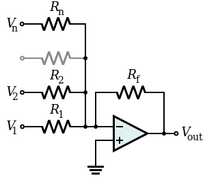
A circuit diagram of a summing amplifier made using an operational amplifier. |
| Date | |
| Source |
Own work This W3C-unspecified
vector image was created with
Inkscape . |
| Author | Inductiveload |
| Permission ( Reusing this file) |
Own work, all rights released (Public domain) |

| I, the copyright holder of this work, release this work into the
public domain. This applies worldwide. In some countries this may not be legally possible; if so: I grant anyone the right to use this work for any purpose, without any conditions, unless such conditions are required by law. |
File history
Click on a date/time to view the file as it appeared at that time.
| Date/Time | Thumbnail | Dimensions | User | Comment | |
|---|---|---|---|---|---|
| current | 04:36, 26 January 2009 |
| 300 × 260 (41 KB) | Inductiveload | {{Information |Description= |Source= |Date= |Author= |Permission= |other_versions= }} |
| 04:14, 26 January 2009 |
 | 300 × 260 (41 KB) | Inductiveload | {{Information |Description=A circuit diagram of a en:summing amplifier made using an en:operational amplifier. :<math> V_\mathrm{out} = - R_\mathrm{f} \left( { V_1 \over R_1 } + { V_2 \over R_2 } + \cdots + {V_n \over R_n} \right) </math> |S |
File usage
The following pages on the English Wikipedia use this file (pages on other projects are not listed):
Global file usage
The following other wikis use this file:
- Usage on en.wikibooks.org
- Usage on et.wikipedia.org
- Usage on fa.wikipedia.org
- Usage on fi.wikipedia.org
- Usage on fr.wikibooks.org
- Usage on hi.wikipedia.org
- Usage on id.wikipedia.org
- Usage on sq.wikipedia.org
- Usage on www.wikidata.org
Metadata
Size of this PNG preview of this SVG file:
300 × 260 pixels. Other resolutions:
277 × 240 pixels |
554 × 480 pixels |
886 × 768 pixels |
1,182 × 1,024 pixels |
2,363 × 2,048 pixels.
Original file (SVG file, nominally 300 × 260 pixels, file size: 41 KB)
| This is a file from the
Wikimedia Commons. Information from its
description page there is shown below. Commons is a freely licensed media file repository. You can help. |
| Description |
A circuit diagram of a summing amplifier made using an operational amplifier. |
| Date | |
| Source |
Own work This W3C-unspecified
vector image was created with
Inkscape . |
| Author | Inductiveload |
| Permission ( Reusing this file) |
Own work, all rights released (Public domain) |
| I, the copyright holder of this work, release this work into the
public domain. This applies worldwide. In some countries this may not be legally possible; if so: I grant anyone the right to use this work for any purpose, without any conditions, unless such conditions are required by law. |
File history
Click on a date/time to view the file as it appeared at that time.
| Date/Time | Thumbnail | Dimensions | User | Comment | |
|---|---|---|---|---|---|
| current | 04:36, 26 January 2009 |
| 300 × 260 (41 KB) | Inductiveload | {{Information |Description= |Source= |Date= |Author= |Permission= |other_versions= }} |
| 04:14, 26 January 2009 |
| 300 × 260 (41 KB) | Inductiveload | {{Information |Description=A circuit diagram of a en:summing amplifier made using an en:operational amplifier. :<math> V_\mathrm{out} = - R_\mathrm{f} \left( { V_1 \over R_1 } + { V_2 \over R_2 } + \cdots + {V_n \over R_n} \right) </math> |S |
File usage
The following pages on the English Wikipedia use this file (pages on other projects are not listed):
Global file usage
The following other wikis use this file:
- Usage on en.wikibooks.org
- Usage on et.wikipedia.org
- Usage on fa.wikipedia.org
- Usage on fi.wikipedia.org
- Usage on fr.wikibooks.org
- Usage on hi.wikipedia.org
- Usage on id.wikipedia.org
- Usage on sq.wikipedia.org
- Usage on www.wikidata.org